Hydrodynamic equations model mud-pulse telemetry transmissions
A closed-loop drilling system, to be effective, requires reliable two-way communication between the downhole module and surface.1 2
Today's drilling industry uses mud-pressure pulse telemetry as one of the most popular and low-cost communication and data transmission methods between the surface and bottom of the wellbore.
Maximizing the data communication rate and transmission distance for mud-pulse telemetry has become important problems for the industry. The authors propose methods that should improve existing mud-pulse measurement and control systems and prove useful to develop new systems.
Various authors have studied mud pulse or wave velocity and attenuation, both theoretically and experimentally.3 Conventionally, however, the industry has viewed the drilling mud as a single-phase fluid and has analyzed mud-pressure pulse attenuation or dampening with a static model.
Liu Xiushan, et al., presented a multiphase flow formula to calculate mud-pulse velocity.4 5 To extend the effort, this work examines the dynamic-transmission behavior of the mud-pressure pulse or wave.
According to fluid dynamics, the authors present a mathematical model and method to simulate drilling-mud pulse or wave transmission behavior.
The results show that mud pulses, up and down along the wellbore, have refraction and reflection components at the boundaries that are similar to damped oscillation.
Hydrodynamic equations
As mud pulses or waves travel along the wellbore, signal attenuation is a function of well depth, mud viscosity, and signal frequency.
Compared with wellbore and drillstring length, the well diameter is small, with high radial stiffness. The mud-pulse transmission channel, therefore, is obviously along the axis of drillstring.
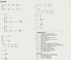
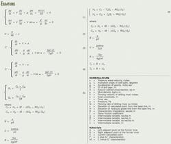
Equation 1 gives the equation of motion and the continuity equation for unsteady flow that can simulate the transmission behavior of mud pulses or waves along the wellbore (accompanying box).
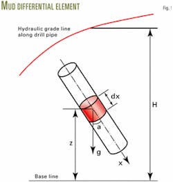
Fig. 1 shows a differential element of drilling mud. To analyze the flow behavior of drilling mud, one can use the elevation of hydraulic grade line from a base line (H) to indicate the pressure (p). Equation 2 expresses the relation between H and p.
Equation 1 is a hyperbolic differential equation group, which the authors solved using a typical method for solving this kind of mathematical problem.
Numerical solution
Equation 1 has partial derivatives in two directions (x and t), which makes finding its solution difficult. By using the system characteristics one can turn the partial derivatives into ordinary derivatives.
A pressure pulse will travel along the wellbore upward and downward simultaneously. The flow parameters at any depth and time will have components of both forward and backward waves that are described as two characteristics, C+ and C-.
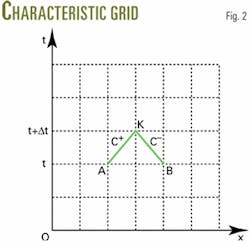
Equations 3 and 4 represent the characteristic equations and the compatible formulas that are perfect differential equations. Solving Equations 3 and 4 first requires visualizing the characteristics in terms of a discrete grid or discrete intervals.
If the length interval for numerical calculation is Δx, the time increment will be Δt =Δx/a. Fig. 2 shows the calculated rectangular grid, with the grid diagonals representing the C+ and C- characteristics.6
Smaller length intervals will yield better numerical precision but the computing time required for the solution will significantly increase. From selected values of Δx, the approach calculates the value of Δt according to a stability criterion.
The drilling-mud flow rates are unknown and change with the C+ and C- characteristics. Numerical approximation is the accepted solution method.
Equation 5 gives the first-order finite difference scheme. The method calculates the current flow parameters at point K from the earlier parameters at adjacent Points A and B.7
If the drilling mud viscosity is very high, the calculated results with the first-order approximation will be not accurate enough and may even be unstable. Equation 6, in this case, gives the second-order finite difference scheme involving iterative calculations.
The computational process generally starts from the steady-flow state and repeats the same series of processing steps until it reaches a predetermined time.
Analysis results
Given the following input data, an example simulates the transmission behavior of mud-pulses travel along a wellbore:
- Drill pipe: D = 108.6 mm, OD = 127 mm.
- Drilling mud: ρ = 1,200 kg/cu m, μ = 5 mPa-sec, Q = 28 l./sec.
- Bit nozzles: two 8 mm and one 13-mm.
- Mud-pulse velocity: a = 1,200 m/sec.
- Well depth: L = 3,000 m.
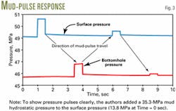
Fig. 3 shows pressure change, as a function of time, at the surface and at the bottom of the well near the vicinity of the drill bit. Equation 6, with the input data above, generated the pressure plots.
Based on the research, the authors have concluded the following:
•Mud-pulse signals have a considerable delay time between the surface and bottomhole, which is the mud-pulse travel time in the wellbore.
•Mud-pulse travel is a process of energy conversion. Compared to the analogy of an insulated electrical conductor or hardwire, mud-pulse attenuation is very high.
•Mud pulses travel up and down along wellbore—they refract and reflex at the boundaries. Similar to damped oscillation, after generation of a pressure pulse, drilling-mud flow will gradually stabilize.
•Mud-pulse attenuation relates to many parameters. In regular drilling operations, however, attenuation increases mainly with well depth, mud viscosity, and signal frequency.
• To improve mud-pulse telemetry depth and data transmission rate, the industry must deal with the twin contradiction of factors that increase signal attenuation. Understanding the physics of the process becomes essential.
With the model and methods presented, the industry can easily simulate transmission behavior of drilling-mud pulses along wellbores.
The process can replace laboratory experiments for improving existing mud-pulse system performance and for developing new drilling-mud pulse systems.
References
- Poli, S., Donati, F., Oppelt, J., and Ragnitz, D., "Advanced Tools for Advanced Wells: Rotary Closed Loop Drilling System—Results of Prototype Field Testing," SPE paper No. 36884, presented at the SPE European Petroleum Conference, Milan, Oct. 22-24, 1996.
- Liu, X., and Su, Y., "Scheme Design of Downward Signaling System," Acta Petrolei Sinica, Beijing, Vol. 21, No. 6, 2000, p. 88.
- Desbrandes, R., Bourgoyne, A.T., Jr., and Carter, J.A., "MWD Transmission Data Rates Can be Optimized," Petroleum Engineer International, June 1987, p. 46.
- Liu, X., and Su, Y., "Study on Transmission Velocity of Mud Pulse Signal," Petroleum Drilling Techniques, Beijing, Vol. 28, No. 5, 2000, p. 24.
- Shi, Z., and Liu, X., "Multiphase technique improves mud-pulse velocity calculations," OGJ, July 1, 2002, p. 45.
- Liu, X., and Su, Y., "Investigation on the Transmission Characteristics of Drilling Fluid Pulse Signal," Oil Drilling & Production Technology, Renqiu, China, Vol. 22 (2000), No. 4, p. 8.
- He, S., and Liu, X., "Analysis of Signal Attenuation for Positive Drilling Fluid Pulse," Drilling & Production Technology, Guanghan, China, Vol. 24 (2001), No. 6, p. 1.
The authors
Xiushan Liu is a professor and deputy director of the engineering and technique division at Sinopec Corp.'s Exploration & Production Research Institute, a visiting professor at CNPC's Key Laboratory of Drilling Engineering, and a part-time professor at Daqing Petroleum Institute in China. He has a BS and an MS from Daqing Petroleum Institute and a PhD from Research Institute of Petroleum Exploration & Development of CNPC, all in petroleum engineering.
Shushan He is a general manager and senior engineer at Jilin Petroleum Group Ltd. of CNPC. He received his BS and MS from Daqing Petroleum Institute and is reading for his PhD at the University of Petroleum in China, all in petroleum engineering. His professional experience includes work as a general engineer of No.1 Drilling Co., a manager of No.3 Drilling Co. at Daqing oilfield, and a general engineer at Jilin Petroleum Group Ltd.
Zhengchao Zhao is a director and senior engineer at Oil Production Institute of CNPC's Liaohe Oilfield Limited Co. He received his BS and MS in petroleum engineering from Daqing Petroleum Institute and is reading for his PhD in hydromechanics at the Institute of Mechanics of the Chinese Academy of Sciences.
