Study outlines optimum ULSD hydrotreater design
ULSD HYDROTREATING—1
A recent study for a grassroots 30,000-b/sd hydrotreater that can produce ultra-low sulfur diesel (ULSD) helped assess the critical process design issues for meeting future ULSD requirements.
The feed, a 70:30 mixture of virgin distillate and FCC light cycle oil, was the basis for a previous Mustang Engineers & Constructors LP study for revamping an existing facility to meet the ULSD specification.1
This first of two articles presents a comprehensive overview of design considerations for grassroots ULSD hydrotreaters. The chemistry of middle distillate sulfur species (see box), reaction process variables, and major factors influencing reactor design are covered.
Engineering aspects of hydrotreater design are discussed, including a suitable operating pressure level that satisfies reaction conditions and the practical limits of piping mechanical design.
Alternative process configurations for ULSD hydrotreaters were studied, along with key design parameters and metallurgical considerations for major equipment.
Part 2, next week, will present process simulations for different process configurations at reactor inlet pressures of 800 and 1,100 psi. We estimated capital costs and life cycle costs for three cases.
Design considerations
The ULSD hydrotreater designer must account for these factors during the front-end design process:
- Feed characteristics and variability.
- Other product-quality requirements, especially cetane index.
- Catalyst selection.
- Optimization of reactor process variables.
- Equipment design requirements.
- Reliability.
- Future off-road diesel sulfur standards.
- Minimizing product contamination.
- Handling of off-specification diesel product.
Process flow
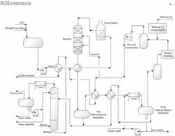
Fig. 1 shows a simplified process flow diagram for a diesel hydrotreater.
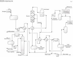
Stripper bottoms heats fresh feed from the surge drum, which then mixes with recycle hydrogen. Reactor effluent further heats the combined feed, which is then heated in the charge heater.
Reactor inter-bed quench may be required depending on the volume of cracked stocks—FCC light cycle oil and light coker gas oil—in the feed. Fig. 1 shows recycle gas used as quench.
Reactor effluent heats the combined feed and flows to a hot, high-pressure separator (HHPS). Vapor from the HHPS heats the recycle gas and stripper charge before cooling in the product condenser and entering the cold, high-pressure separator (CHPS).
Wash water, injected upstream of the product's condenser, helps remove ammonium hydrosulfide. HHPS liquid combines with heated CHPS liquid and flows to the product stripper.
Vapor from the CHPS contacts with amine in a scrubber for H2S removal and flows to the recycle compressor suction drum. Makeup hydrogen is compressed and combines with recycle gas in the suction drum. The compressor suction drum can purge some recycle gas to improve recycle gas hydrogen purity. The quantity depends on the reactor's hydrogen-partial-pressure requirements and makeup hydrogen purity.
In the product stripper, superheated steam feeds the tower's bottom and helps remove H2S. Stripper overhead vapors condense and flow to the stripper accumulator. Accumulator vapor and liquid, known as wild naphtha, are processed in offsite facilities.
Stripped ULSD product supplies heat to the feed stream and then flows to drying facilities, which can be a coalescer-salt dryer or vacuum drying system.
Feed, product characteristics
Sulfur, nitrogen, and aromatics have the greatest impact on the ULSD facility design. Feed nitrogen has a significant impact on the operating pressure. The refiner must remove nitrogen to essentially the same level as sulfur to meet the ultra-low sulfur target.
This means that the catalyst and hydrogen partial pressure must be consistent with a high nitrogen-removal operation.
Light coker gas oil and FCC light cycle oil normally contain most of the feed nitrogen. Feed aromatics content governs chemical hydrogen consumption at the low space velocities and high hydrogen partial pressures required for ULSD production.
Product cetane or gravity generally determines the amount of cracked stocks that a refiner can include in the feed.
There is a small increase in the gravity and cetane index during the hydrotreating reaction.
If a significant improvement in cetane (3-5 numbers) or gravity is required, a multistage design using aromatics saturation catalysts in the second stage may be a more economical option. The magnitude of improvement in gravity and cetane determines this design choice.
Design product sulfur is a key target, not only from a process design standpoint, but also for offsite storage and transfer considerations.
Most new and revamp facility designs are for a product sulfur content of 8-10 ppm (wt).
Refiners should pilot test the feed to confirm reaction process conditions. Testing for variations in feed characteristics, especially the FCC light cycle oil and coker light gas oil's back-end distillation, is important because product separation in these facilities is notoriously poor.
This can result in a temporary spike in the most difficult-to-treat sulfur compounds in the hydrotreater feed and requires a higher reactor temperature. This increases the catalyst deactivation rate and directionally reduces cycle length.
Reaction process variables
Key reaction process variables include:
- Space velocity.
- Hydrogen partial pressure.
- Makeup hydrogen purity.
- Ratio of total hydrogen to chemical hydrogen consumption.
- Cycle length.
- Reactor temperature.
Refiners can use a nickel-molybdenum catalyst for feeds that have high aromatics or nitrogen; an appropriate selection of graded catalysts in the bed's top will mitigate reactor pressure buildup.
Refiners must optimize reactor space velocity, hydrogen treat gas quantity, hydrogen partial pressure, and reactor temperature during the process design phase for a given cycle length and treating severity.
Catalyst deactivation rate falls with increasing hydrogen partial pressure; therefore, the space velocity can increase for a constant cycle length. This is, however, at the expense of higher hydrogen consumption.
Another important variable is the ratio of total hydrogen supplied to chemical hydrogen consumption. This value should be 5-6 for feeds with significant quantities of cracked stocks. This ratio is normally less important during the process design, but it can control the design hydrogen-circulation rate, especially when a refiner exclusively uses high-purity makeup hydrogen.
When setting the hydrogen partial pressure and total operating pressure, one should be aware that the alloy piping flanges limit the reactor pressure, especially when the feed contains significant quantities of cracked stocks. This includes piping between the feed exchangers and feed heater, between the heater and reactor, and between the reactor and combined feed exchangers.
Piping is normally a 300-series stainless steel; for 600-psi flanges this corresponds to a maximum operating pressure of around 800 psi at the reactor inlet. For 900-psi flanges, the reactor operating pressure can increase to about 1,100 psi. These pressures account for relieving conditions.
These criteria should not necessarily govern a refiner's selection of operating pressure; however, pressures barely exceeding these limits and requiring the next-higher-rated ANSI flange class are costly.
Actual pipe wall thickness is calculated from design conditions; the limiting value is used for the piping specification in the reactor loop's alloy sections.
Actual pipe materials can also be 316, 321, and 347 grades of stainless steel. Type 347 has a higher allowable stress value than the other grades but is normally more expensive. Availability and delivery time for the various stainless components are also a major consideration.
The existing equipment and reactor loop's piping limit the hydrogen partial pressure in revamp designs. A higher treat gas rate can increase the hydrogen partial pressure; this is usually limited due to an associated increase in the reactor loop's pressure drop and the corresponding maximum operating pressure of system components.
Lower-purity makeup hydrogen requires higher hydrogen circulation rates to maintain a target hydrogen partial pressure; it may even require a purge stream from the cold separator. If makeup hydrogen purity is too low, there is no combination of recycle rate and purge that will achieve the target reactor outlet partial pressure.
For a revamp design, increasing makeup hydrogen purity is the most effective way to increase the hydrogen partial pressure.
Catalyst cycle lengths of 24-36 months are typical for new designs. This is because, at some point, factors other than catalyst activity (such as reactor pressure drop) will limit the cycle. For a fixed space velocity, cycle length increases with a higher hydrogen partial pressure.
Maximum reactor outlet temperature at end-of-cycle catalyst conditions is usually 725-750° F. to avoid aromatics saturation equilibrium constraints and to maintain product color. The amount of cracked stocks in the feed and the crude source also influence this temperature.
Hydrotreating catalyst performance correlations for reactor temperature is usually based on the weighted average bed temperature. WABT is the reactor inlet temperature plus two thirds of the reactor temperature rise. Quenching limits the temperature rise to 40-50° F. in each bed.
For a 50° F. temperature rise and a 725° F. maximum reactor outlet temperature, the end-of-run WABT is (725-50) + 2/3(50) = 708° F.
The start-of-run WABT must be high enough to remove the required amount of sulfur and nitrogen. The catalyst deactivation rate at the design space velocity and hydrogen partial pressure determines cycle length. During the cycle, WABT will increase 30-50° F. with lower deactivation rates at higher hydrogen partial pressures.
Reactor design
A superficial mass velocity set at 2,000-5,000 lb/hr/sq ft determines the initial reactor diameter. A value of 3,500 allows for a reasonable turndown rate and some upside allowance. Mass flow includes all hydrocarbons and hydrogen at the reactor inlet.
The refiner should consider a two-train design if the required reactor diameter is larger than could be shop fabricated and shipped to the plant site—usually 12-14 ft for overland shipment. For diesel hydrotreaters, this is normally 30,000-40,000 b/sd for each reactor train.
Refiners with adequate water access and dock facilities can consider larger reactors and larger single-train capacities.
An appropriate correlation8 estimates the pressure drop for two-phase flow through the reactor. The pressure drop calculation should also include inter-bed quench.
Catalyst physical properties, including void fraction and equivalent particle diameter, have a significant impact on reactor pressure drop. To ensure good distribution in the catalyst beds, most ULSD reactors are dense loaded instead of sock loaded. The clean pressure drop should be 0.5-1.0 psi/ft of catalyst bed.
For a required catalyst volume, bed heights are either based on the heat of reaction and maximum temperature rise or set at 30-40 ft. The designer then estimates the clean pressure drop for each bed.
The designer determines the maximum overall pressure drop when designing the bed support and compares it to the catalyst crush strength, which is the sum of:
- Fouled bed pressure drop at 175% of calculated clean drop.
- Dead weight of catalyst and support material.
- Coke deposits at 30% of catalyst dead weight.
- Liquid holdup.
- 15-psi allowance for depressurization.
Pressure drops for the feed distributor and redistributors, quench internals, and collector are added to the bed values to provide the overall fouled-reactor pressure drop. For ULSD, the feed distributor and redistributor design is crucial for obtaining the target product sulfur level.
Several designs provide internal reactor quench to limit the temperature rise. The normal method is to use hydrogen-rich recycle gas. Quench gas also causes liquid vaporization in the reactor, which provides an extra heat sink for heat removal.
Another less-common approach is to recycle CHPS liquid to the reactor. The quench limits the reactor bed temperature rise to 40-50° F.
Reactor metallurgy is typically 11/4-chrome, 1/2-molybdenum with 1/8-in. 347 stainless overlay or cladding. The metallurgy choice often depends on the vessel thickness, which affects the cost. Cladding is usually more economical for vessels with a wall thickness up to about 4 in. An overlay is normally used with thicker walls.
Feed exchangers
Feed exchangers are generally specified to optimize heat economy; however, enough duty should be allowed so that the charge heater has a reasonable amount of turndown and overall heat-balance control.
Feed exchange should not be more than 80-85% of the total duty needed to heat the feed to the reactor temperature at end-of-cycle conditions.
The reactor feed-effluent exchanger's mechanical design requires minimal leakage. Many refiners prefer a pull-through tube bundle with a floating head because it is easier to clean; however, the floating head cover is a potential leak source. A U-tube bundle avoids this potential problem and is less expensive.
Tubes should be seal welded to the tube sheet to prevent leaks from the rolled tube joints.
Material selection for feed-effluent exchangers is based on predicted corrosion rates. Feed-effluent exchangers have several shells in each train with varying metallurgies. Cold shells are all carbon steel. Intermediate-temperature units normally have 11/4-chrome shells and 400-series tubes. Hot shells are 11/4-chrome with 300-series stainless cladding and 300-series stainless tubes.
Charge heater
The feed heater's normal duty should not be less than 20% of the combined feed duty to the reactor's inlet temperature at end-of-cycle conditions; this allows for turndown and heat balance control. A design margin of 10% of the combined feed exchanger duty accommodates accelerated exchanger fouling.
The number of heater passes should match the number of parallel feed-effluent exchanger trains. The refiner can flow control feed and recycle hydrogen for each train upstream of the exchangers. This prevents maldistribution of the two-phase stream entering the heater passes.
The limit for one heater pass is 15,000-18,000 b/sd of fresh feed at typical diesel hydrotreater conditions. This limit is based on a maximum 8-in. diameter heater tube and an overall pressure drop of 40-50 psig.
Heater tube metallurgy is typically 347 stainless steel.
Reactor-product separation
Several alternative arrangements can handle reactor effluent after the combined feed exchangers.
In general, refiners must decide whether to use a HHPS in addition to a CHPS, or a CHPS only. The HHPS usually operates around 500-550° F. and, therefore, the vapors can heat recycle gas and cold separator liquid.
A HHPS improves overall heat economy and results in smaller product stripper and auxiliary equipment. This arrangement also improves oil-water separation in the CHPS.
For heavy gas oil hydrotreating, a hot separator is necessary for adequate oil-water separation. This is less of a concern for diesel hydrotreating unless there are significant quantities of cracked materials, which decrease API gravity.
Disadvantages of this design are a 5-10% lower recycle gas purity that requires more horsepower in the recycle hydrogen compressor. Refiners can add a HHPS to debottleneck an existing hydrotreater that is hydraulically limited in the reactor loop. This revamp would require, however, a modest increase in inlet flow and power for the recycle compressor.
Other options include adding hot and cold low-pressure separators. These designs marginally unload the upper part of the stripper and improve LPG recovery.
HHPS separator base material is 11/4-chrome 1/2-molybdenum, normally with a clad or overlay lining, which is 300 or 400-series stainless depending on the actual predicted corrosion rate.
The CHPS is carbon steel resistant to hydrogen-induced cracking. A 300-series stainless steel mesh pad helps coalesce the wash water. The boot is also hydrogen-induced-cracking resistant steel with a 1/4-in. corrosion allowance.
Reactor products condenser
A final condenser provides cooling before liquid and vapor separation regardless of the reactor product separator configuration. An air cooler is typically used, sometimes supplemented with a water-trim cooler.
Piping and equipment metallurgy in this area requires special attention due to the presence of ammonia and H2S in the reactor effluent. When this stream cools, these two compounds combine to form ammonium hydrosulfide, which condenses as a solid on inlet piping and in cooler tubes.
Recirculating wash water, injected before the cooler, introduces a corrosive aqueous solution in the stream to prevent plugging and under-deposit corrosion.
Tube metallurgy selection is based on ammonia and H2S in the effluent. The designer should ensure a target maximum value for Kp of 0.15 before choosing alloy metallurgy, where:9
Kp = mole % H2S x mole % NH3
The designer should also:
- Determine makeup water quantity to limit ammonium hydrosulfide concentration in the condensed water phase to 4 wt %. One must assume equal molar amounts of ammonia and H2S in the CHPS water and that essentially all ammonia dissolves in the water.
- Determine the quantity of circulating water to ensure that 25% of the total water injected in the liquid phase is upstream of the condenser.
- Limit the mixed-phase velocities in the piping and tubes to 20 fps for carbon steel and 30 fps for alloys. The minimum velocity should be 10 fps.
- Provide symmetrical piping into and out of the condenser.
- Ensure that the wash water source is a stripper dedicated to hydrotreating spent wash water if stripped sour water is used.
- Ensure that wash water is injected into the main effluent line upstream of the condenser, or independently into each air cooler nozzle through a distribution device like a spray nozzle or restriction orifice. Injecting into piping provides more time for mixing and vaporizing the water and is less expensive. Injection into individual air condenser nozzles ensures good distribution in each air cooler bay.
Typical alloys, if required, are Incoloy 800 or 825, and duplex stainless steel 2205.
Compression
Inlet flow and head requirements determine the recycle compressor design. Adequate suction flow is required for a centrifugal compressor, and the head should be low enough to limit the number of stages so that only a single body machine is needed; this is usually a maximum of 10 stages.
In the past, most diesel hydrotreaters had an inadequate volume of recycle gas for a centrifugal compressor. New, larger ULSD hydrotreaters that circulate 3,000-5,000 cu ft of gas/bbl of feed are candidates for centrifugal compressors.
A reciprocating compressor used for recycle normally also provides makeup service in a multiple-throw machine. For reciprocating compressors greater than 500 hp, two 60% capacity machines are typically used. For smaller compressors, two 100% units are used.
Makeup compressor discharge feeds to the recycle compressor suction or discharge.
Makeup gas flowing to the suction increases recycle gas purity and volume, and decreases the molecular weight. This is a potential problem for a centrifugal recycle compressor because the lower molecular weight requires more head and potentially more stages.
This is not as serious for a reciprocating machine; however, higher hydrogen purity increases the discharge temperature, which is limited to 275° F. per API-618.
Makeup gas normally feeds to the recycle compressor discharge unless it needs an additional stage of makeup compression. This has the advantage of maintaining some hydrogen flow through the reactor loop in case of a recycle compressor emergency outage.
Reactor-loop hydraulics
A hydraulic profile for the reactor loop provides the recycle compressor head requirements and establishes the design pressure of piping and equipment.
Reactor inlet pressure is set based on conditions that the catalyst supplier establishes, and the pressure limits of standard piping flanges.
Two case studies are presented in Part 2 for reactor inlet pressures of 800 and 1,100 psig.
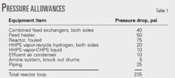
Table 1 shows a typical allowance for reactor-loop equipment and piping pressure drop for the 1,100-psig case.
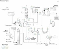
Fig. 2 shows a point-to-point pressure profile for normal operations and for the relieving case in which the CHPS is 10% greater than the operating pressure.

Table 2 shows maximum pressures at relieving conditions and typical design temperatures for critical piping services in the reactor section compared to a maximum allowable pressure for 900-psi, type-321 stainless flanges.
Table 2 shows that the assumed pressure profile is consistent with 900-psi flanges in the reactor loop's alloy piping. The relieving pressure profile sets the design pressure for equipment in the reactor loop.
Early in the design process, the designer develops a sized equipment list that allows for plot plan studies. The designer checks preliminary reactor-loop pipe sketches and rechecks allowances for piping pressure drops before specifying the recycle compressor.
The designer checks reactor-loop hydraulics a final time after receiving equipment vendor information and after completing piping isometrics for the reactor loop.
We established design pressures in the reactor loop assuming the CHPS relief valve set pressure is 10% higher than the normal operating pressure. The refiner can set this margin at 5% with a pilot-operated relief valve, which will lower the reactor loop's design pressures.
A 10% margin in a grassroots facility allows for future capacity increases while staying within equipment design pressure limits. API Recommended Practice 521, Appendix G recommends a design pressure of 105% of the settling-out pressure, which would make the design pressure about 115% of the normal operating pressure.
While the designer is establishing equipment design conditions, insufficient information exists to calculate the settling-out pressure accurately. When the heat and material balances and process flow diagram are completed, however, one can use preliminary equipment sizing information, assumptions about pipe quantities, and the reactor loop's pressure profile to estimate the settling-out pressure.
When actual equipment and piping design information is available, one can re-estimate the settling-out pressure to determine the margin available compared to the CHPS relief valve set point. If the settling-out pressure exceeds the set pressure, a stepwise calculation or dynamic simulation can estimate the relief rate.
Product stripper
The product stripper removes H2S and light hydrocarbons from the ULSD product. Light material removal must be high enough to meet a flash-point specification of 140° F. This ensures removal of nearly all H2S.
The stripper requires about 30 trays. Overhead products include sour gas, unstabilized naphtha, and sour water. The design also includes equipment for intermittently water washing the condenser.
Steam or vapors from a fired reboiler serve as the stripping medium. Due to temperature constraints of about 700° F. maximum, the stripper operating pressure is limited to 40-50 psig for a fixed reboiler.
Unless the refinery has a low-pressure gas recovery system, a small compressor and spare are needed to handle the offgas.
A steam stripper can operate at pressures greater than 100 psig, which allows routing into an existing refinery sour fuel gas system.
Diesel product from a steam stripper must have all water removed. Vacuum drying or coalescing followed by salt drying can accomplish the water removal. If this type of system already exists, the steam-stripping option has a lower capital cost vs. a fired reboiler. A steam-stripped tower is also a little smaller than a reboiled tower.
If the product drying system is not in place, the refiner should consider the fired reboiler option. It will also create less sour water to process.
Product stripper material is killed carbon steel with 410 stainless steel trays and caps. The overhead condenser and receiver are hydrogen-induced-cracking resistant steel. The overhead receiver boot has a 1/4-in. corrosion allowance.
Feed filtration
Although distillate stocks are relatively clean, feed filtration is important to mitigate exchanger and reactor plugging. A cartridge filter with 25-mm retention is typical for this application. Cracked feeds should feed the hydrotreater hot from the upstream facilities or from gas blanketed storage.
Ultra-low sulfur diesel
In mid 2006, the US Environmental Protection Agency will begin enforcing rules that mandate a maximum sulfur content of 15 ppm (wt) for on-road diesel fuel. Refiners are considering several strategies to comply with this rule:
Revamping existing facilities commissioned in the early 1990s that now meet the low-sulfur diesel specification of 500 ppm (wt) sulfur.
Constructing grassroots facilities to meet the new specification.
Executing various combinations of new and revamped facilities.
The problem
Middle distillates contain many sulfur species, including mercaptans, sulfides, thiophenes, and aromatic sulfur compounds.
Sterically hindered dibenzothiophenes are a group of aromatic sulfur compounds that are most difficult to remove; they constitute a large fraction that remains in diesel after hydrotreating to the current specification 500 ppm (wt). This is particularly true for diesel fuels that contain significant quantities of cracked stocks, like FCC light cycle oil, that contain a large concentration of aromatic sulfur compounds.
Effective removal of these species requires tailored catalysts and process conditions. Refiners must also consider other factors, such as feed nitrogen content and aromatics equilibrium. These issues have been addressed in detail in the literature.2-7
References
1. Palmer, R.E., Ripperger, G.L., Migliavacca, J.M., "Revamp your hydrotreater to manufacture ultra low sulfur diesel fuel," presented to the 2001 NPRA Annual Meeting, Mar. 18-20, New Orleans, paper AM-01-22.
2. Leliveld, B., Mayo, S., Miyauchi, Y., and Plantenga, F., "Elegant solutions for ultra low sulfur diesel," presented to the 2001 NPRA Annual Meeting, Mar. 18-20, New Orleans, paper AM-01-09.
3. Brevoord, E., Gudde, N., Hoekstre, G., Mayo, S., and Plantenga, F., "ULSD real life: Commercial performance of Stars and Nebula technology," presented to the 2002 NPRA Annual Meeting, Mar. 17-19, 2002, San Antonio, paper AM-02-38.
4. Landue, M.V., Catalysis Today, Vol. 36 (1997), pp. 393-429.
5. Piehl, R.L., "Refiners tame effluent air-cooler corrosion," OGJ, Aug. 18, 1975, pp. 119-20.
6. Torrisi, S., "Proven best practices for ULSD production," presented to the 2002 NPRA Annual Meeting, Mar. 17-19, 2002, San Antonio, paper AM-02-35.
7. Schmidt, M., "Premium performance hydrotreating with Axens HR 400 series hydrotreating catalysts," presented to the 2002 NPRA Annual Meeting, Mar. 17-19, 2002, San Antonio, paper AM-02-57.
8. Larkins, R.P., White, R.R., and Jeffery, D.W., "Two Phase Concurrent Flow in Packed Beds," AICHE Journal, June 1961, pp. 231-39.
9. Knudsen, K.G, Cooper, B.H., and Topsoe, H., "Catalyst and Process Technologies for Ultra Low Sulfur Diesel," Applied Catalysis A: General, Vol. 189 (1999), pp. 205-15.
Based on a presentation to the 2003 NPRA Annual Meeting, Mar. 23-25, 2003, San Antonio.

The authors
Leslie J. Harwell is a senior consulting process engineer at Mustang Engineers & Constructors LP, Houston. He is primarily involved in ultra-low sulfur projects and midstream gas processing. Harwell has also worked for Fish Engineering Corp. and Litwin Engineering & Construction Inc. He holds a BS (1967) in chemical engineering from the University of Texas, Austin. Harwell is a registered professional engineer in Texas and a member of the Gas Processors Suppliers Association.

Shrikant (Sam) Thakkar is a senior specialist for ChevronTexaco Corp., Bellaire, Tex. He previously worked for Mustang Engineers & Contractors LP (when this article was written). He holds a BS (1981) in chemical engineering from Bombay University.

Stan Polcar is a principal process engineer for Mustang Engineers & Constructors LP. He has also worked for Litwin Engineering & Construction Inc. and The Pritchard Corp. Polcar holds a BSc (1968) in chemical engineering from Case Western Reserve University, Cleveland. He is a registered chemical engineer in Texas.

R.E. Palmer is the manager of downstream process engineering for Mustang Engineers & Constructors LP. He is responsible for process design and marketing support for all refining, petrochemical, and chemical projects. He has led numerous studies, technology evaluations, and projects relating to clean fuels production. Palmer previously spent 23 years with Litwin Engineers & Constructors Inc. and 5 years with Conoco Inc. He has a BS in chemical engineering from the University of Missouri, Rolla.

Pankaj H. Desai is the new business development manager for Akzo Nobel Catalysts LLC, Houston. He joined Akzo Nobel in 1980 and has held various positions in hydroprocessing and FCC catalyst research and development. Desai holds a BTech degree (1974) in chemical engineering from Indian Institute of Technology, Kanpur, and a PhD in chemical engineering from the University of Houston.