Chinese gas pipeline overcoming geographic obstacles en route to 2004 start-up
Under construction since October 2001, PetroChina Co. Ltd.'s West-to-East natural gas pipeline is moving toward a 2004 completion of the approximately 3,800 km, 1,016-mm (40-in.) mainline.
This third and concluding article describes some of the major challenges and obstacles faced by the project and how they are being overcome.
The second article (OGJ, May 26, 2003, p. 54) described the project's design and specifications, significant material suppliers and contractors, and construction plan, schedule, and management. Part 1 (Mar. 17, 2003, p. 68) provided an overview of the project, its rationale and status.
The pipeline route crosses topographical features that create major and unique construction challenges including three crossings of the Yellow River, a crossing of the Yangtze River, tunnel crossings of mountains, crossing of the vast loess plateau in central China, and crossing of waternet areas in eastern China.
Yellow River crossing
null
The 40-in. mainline crosses the Yellow River at three locations (see Fig. 1, OGJ, May 26, 2003, p. 54) utilizing different design and construction methods:
- Aerial crossing at Zhongwei: 536 m.
- Tunnel crossing at Yangshiguan: 518 m.
- Pipe-jacking and four horizontal directionally drilled crossings at Zhengzhou: 7,645 m (total):
—Pipe-jacking from Shaft 1 to Shaft 3 = 1,175 m.
—Pipe-jacking from Shaft 3 to Shaft 4 = 1,166 m.
—Pipe-jacking from Shaft 5 to Shaft 4 = 1,259 m.
—HDD crossings of 684 m, 1,088 m, 1,133 m, and 1,140 m.
The aerial crossing at Zhongwei is designed utilizing a truss structure on concrete piles installed in the riverbed to support the pipeline.
Construction of this aerial crossing was initiated in April for completion by yearend.
The tunnel crossing at Yanshiguan was designed utilizing a conventional manually excavated tunnel lined with concrete. The tunnel is about 3.55 m high and 3.7 m wide. It was completed in March 2003, and installation of the pipeline completed in June.
Complex geotechnical conditions were encountered during the blasting and excavation of this tunnel that created fissures and large water leaks to the tunnel from the river and required use of grouting methods at several locations to reduce the infiltration of water to allow construction to continue.
Water infiltration in the tunnel dictated that the tunnel be permanently flooded with water, although it can be dewatered with high-capacity pumps for future inspection or maintenance to the pipeline.
The three pipe-jacks at Zhengzhou are designed utilizing a series of 15-m diameter concrete caisson shafts (Shafts 1, 3, and 5; Fig. 1) and a smaller 8-m diameter caisson (Shaft 4) connected with 1,800-mm external diameter steel casing pipe. The casing pipe is being installed with three DH-1500 slurry pipe-jacking machines using a laser guidance system for each machine for correct steering controls.
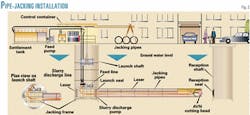
Pipe-jacking is a technique of installing pipes by driving a line of them through the ground with hydraulic rams from a prepared jacking pit or shaft (Fig. 2).
Excavation is carried out at the forward shield end of the machine with a cutting head similar to a large drill.
The excavated material together with slurry is then pumped out via a pipeline to the surface for separation and then reinjected into the pipeline.
The pipe is pushed from the jacking pit. After a full pipe length is pushed into the ground, a new pipe is placed in the pit and the process repeated. A lubricant is used on the outside of the pipe to reduce the friction along the pipe.
For long lengths of pipe, as in this case, intermediate jacking stations may be used whereby the total length of pipe is moved progressively section by section, thus reducing the force required at the jacking pit or shaft to advance the pipe.
The pipeline will be installed by welding and pushing the pipe inside the casing pipe from each caisson location.
In addition to these three pipe-jack crossings, this Yellow River crossing also includes four horizontal directional drills varying from 684 m to 1,140 m long across the vast Yellow River floodplain to connect with the pipe-jacking crossing.
The horizontal directionally drilled crossings were completed in 2002, and the pipe-jacking work has been ongoing since the fall of 2001.
This crossing has experienced extremely complex geological conditions in sinking caissons No. 4 and No. 5 delaying its completion.
A ground freezing technique was used to finish the sinking of caisson No. 5 and the steel casing has been completed between caissons Nos. 1 and 3, 3 and 4, and is progressing between Caissons 4 and 5.
To meet its in-service completion schedule, however, the pipeline project has implemented and completed a backup plan and installed 4,000 m of 406.4-mm (16-in.) temporary pipeline utilizing two horizontal directional drills totaling 3,200 m long.
Yangtze River crossing
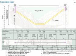
The 1,992-m tunnel crossing of the Yangtze River is designed as a 3.8-m ID concrete lined tunnel between a 15 m by 7.5 m (internal dimensions) concrete entry shaft on the river's south bank and a 15 m by 7.5 m concrete reception shaft on the river's north bank. The tunnel is designed to accommodate other future utilities.
At its deepest point, the tunnel is 42 m beneath the Yangtze River (water level) and 12 m from the river bed (Fig. 3). The Taiwanese contractor completing the design and construction of the project is CTCI Corp.
The permanently maintained tunnel includes ventilation, pumping, and lighting system and walkway (Fig. 4; photograph from Universal Ensco).
The tunnel will be permanently maintained and include a ventilation, pumping, and lighting system and a walkway for access by operations personnel (Fig. 4). The tunnel is being bored with a 4.57-m diameter slurry-type tunnel boring machine manufactured by Mitsubishi Heavy Industries Ltd. that includes an erector that automatically installs the tunnel precast concrete segments for the permanent lining of the tunnel.
The pipeline will be installed by double-jointed pipe being moved to the middle of the tunnel, and two crews welding the pipe in place simultaneously from the center of the tunnel outward to the entry and exit shafts.
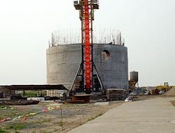
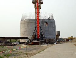
The cutting head for the 4.57-m diameter slurry-type tunnel boring machine was manufactured by Mitsubishi Heavy Industries Ltd. (Fig. 5; photograph from Universal Ensco).
The tunneling machine consists of the cutting head (Fig. 5), an erector that handles the segment placement, and a backup train that is towed along as the tunnel boring machine advances. Attached to this backup are the power supply, hydraulic motors, and various slurry pumps that extract the excavated material via a pipeline laid along the length of the tunnel eventually going to the surface for separation from the slurry and excavated material with a special separation process.
Behind the boring machine backup, which is about 90 m long, are such services as slurry pipes, water pipes, grouting pipes, electricity supply cables, tunnel lighting, computer cables, and ventilation ducting which are continually being extended as the tunnel advances.
Segments are delivered to the ring build area via a narrow-gauge track with an electric locomotive and segment carrying cars. Trucks haul spoil materials from the south bank's entry shaft to approved disposal sites.
This crossing ran into difficult and complex geological conditions in sinking the entry shaft on the south bank and required soil treatment by special grouting techniques; these delayed its completion.
Additionally, the tunnel boring operation encountered cobbles and pebbles together with stiff clay that required use of a rock crusher. The stiff clay together with the large cobbles frequently blocked the slurry pipe system and delayed the progress of the tunneling operation.
As of July 1, the tunnel had completed boring 1,863 m or 93% complete. Completion of the tunnel is imminent; pipe installation will take place in November 2003.
To ensure meeting its in-service completion schedule, however, the West-to-East Gas Pipeline project has implemented and completed a backup plan and installed 7,910 m of 406.4-mm temporary pipeline using two horizontal directional drills totaling 2,728 m long.
Mountain tunnel crossings
null
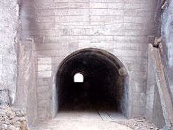
The 40-in. mainline crosses three mountain ranges; sixteen mountains were crossed with manually excavated tunnels lined with concrete (Fig. 6). These mountains were very steep and narrow and could be installed more economically by tunneling vs. conventional pipeline construction over or around the mountains.
The tunnels are about 3.1 m high and 3.2 m wide. Most tunnels primarily passed through soils, but rock in some tunnels required blasting for excavation. All of the mountain tunnels were completed and the pipeline installed in 2002.
Loess plateau crossing
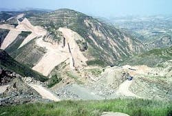
The 40-in. mainline crosses the loess plateau of central China for approximately 504 km. Loess soils are extremely complex and were blown and redeposited over hundreds of years during dust storms from arid areas. These soils only exist in a few areas of the world and have unique characteristics including being highly erodable once disturbed.
Another unique characteristic is an almost vertical angle of repose.
The mainline crosses the loess plateau of central China whose soils are extremely complex and highly erodable once disturbed (Fig. 7; photograph from Universal Ensco).
This results in a plateau scored with ravines and gorges resulting in steep and undulating terrain with narrow ridges (Fig. 7).
Also, unlike mountains, there is hardly any continuity in ridges and valleys that facilitate pipeline routing for extensive lengths along these features.
Construction through this area required installation of 18 aerial crossings, use of more than 1,300 induction bends for both vertical and horizontal bends in the pipeline, massive cuts and fills of soil to facilitate construction of the pipeline, and a significant quantity of hydraulic protection to the restored construction right-of-way to prevent future erosion and exposure of the pipeline.
A large portion of this line pipe had to be strung and welded in the ditch due to the steep terrain (slopes of greater than 50°). The contractor on Section 17 removed the turret from a military tank (with its low center of gravity) and modified it to haul and string pipe very successfully in the steep grades.
Waternet areas
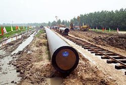
The mainline crosses waternet areas that consist of networks of irrigation canals and ditches as well as rice farming and fish ponds (Fig. 8; photograph from Universal Ensco).
The mainline crosses about 268 km of waternet (areas with networks of irrigation canals and ditches) with intensive farming of rice and ponds for producing fish and fresh water pearls (Fig. 8). Waternet areas consist of extensive areas of flooded lands and high groundwater.
Pipeline construction work was further complicated by the substantial use of irrigation canals and ditches for boat transportation and commerce by local residents.
One positive characteristic of the waternet is that its soils are generally clay material, which slows water infiltration and facilitates dewatering with pumps.
Construction crews were able to build drainage and totally pump and dry out some areas including fish ponds, allowing heavy equipment to move through them without becoming bogged down in mud.
Design of the fiber optic high-density polyethylene (HDPE) conduits called for a first backfill of the pipeline with only 0.3 m of spoil above the line pipe, the HDPE conduits to be installed in the trench above the pipeline, and a final second backfill placed to natural ground.
The first backfill depth, however, was insufficient to keep the pipeline from floating once dewatering pumps were removed in some areas, and the design had to be changed to backfill the pipeline completely and install the HDPE conduits in a separate trench adjacent the pipeline in the waternet area.
The fish pond crossings created unique challenges. These ponds were typically about 2 m deep. Many crossings required damming a portion of the pond to segregate the pipeline crossing to allow continued operation of the fish pond.
Others had very little workspace due to residences and businesses being close to the fish ponds. Chinese designers have not chosen to use concrete coated pipe; getting the pipe into place and installing concrete weights proved to be a difficult challenge.
The significance of the work in the waternet areas is shown by the following: about 28 km of fish ponds and 362 watercourse crossings.
Construction techniques included installation of pipe using push-pull methods to float the pipe into place, pumping to dewater the trench line, and transportation of pipe and concrete weights along the construction right-of-way using narrow-gauge rail and pontoons in flotation ditches since availability of construction mats is limited in China.
