Hybrid architecture provides solution for deepwater developments off West Africa
To develop their deepwater West Africa discoveries, several operators have opted for a hybrid architecture that includes a dry-tree floating structure, such as a tension leg platform (TLP), adjacent to a floating production, storage, offloading (FPSO) vessel.
In this design, the dry-tree unit provides the drilling functions while the adjacent FPSO provides processing, utilities, and storage. This architecture has emerged as a development option of fields discovered in areas with little or no pipeline infrastructure and for fields requiring considerable reservoir management.
In the case of a TLP, the metocean conditions off West Africa cause the optimum TLP configuration to differ from the TLPs designed for the Gulf of Mexico. TLPs off West Africa must have different deck and hull configurations, global performance, and tendons.
Field development strategy
Field development strategies highly depend on reservoir characteristics and local infrastructure. An FPSO with subsea tiebacks is the typical choice for reservoirs with a large areal extent. On the other hand, if the well pattern is compact, a dry-tree option, such as a TLP, provides better reservoir management and extraction solution.
A comparison of typical TLP applications for the Gulf of Mexico and West Africa illustrates the importance of local infrastructure.
The Gulf of Mexico, except in the deepest water, has an existing product transportation infrastructure of pipelines. As a result, TLP designs for the larger reservoirs include all required functions for drilling and production, while pipelines conveniently export processed oil and gas to shore.
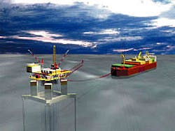
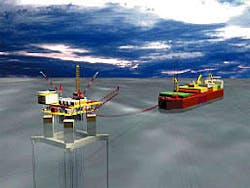
West Africa, on the other hand, lacks a pipeline infrastructure. In this case, product storage and transport becomes an issue and the architecture of the development includes a hybrid system with both a TLP and FPSO (Fig. 1).
The TLP's primary function is as a drilling unit, housing all associated facilities for supporting and manning the drilling operation. The TLP provides dry-tree access to most wells and supports some wet-tree tiebacks. To begin development drilling earlier, one can install the TLP many months prior to the arrival of the FPSO.
Upon installation, the FPSO provides the processing, utilities, product storage, and offloading functions.
The final installed configuration has the TLP and FPSO closely moored together and joined with a series of product transfer lines and power cables.
TLPs
To date, the industry has installed 14 TLPs. In 1984, Conoco U.K. Ltd. installed the first, the Hutton platform, in the North Sea in 486 ft of water. Fig. 2 illustrates the growth of TLP applications in increasing water depths since Hutton. At the time of this article, the Agbami project has not been awarded and a TLP for this project is uncertain.
Compared to other floaters, the TLP suppresses wave-induced motions with its different mooring system, which is vertically oriented and consists of tubular steel members called tendons. The tendons are highly tensioned, using excess buoyancy of the platform hull.
This tensioned system limits horizontal movement of the TLP to a small percentage of water depth. The high tendon axial stiffness also reduces the system's vertical natural periods to a level much less than the dominant wave energy.
As a result, dynamic amplification of vertical motion is almost nonexistent and the platform experiences very small heave, roll, and pitch motions. Essentially, the platform's vertical motions correspond to the stretch in the tubular steel tendons. This is a major plus for drilling operations because downtime is minimized. For even the largest Gulf of Mexico hurricane waves of 71 ft, vertical platform motions are only a few inches.
Two TLPs are currently in the detailed design and delivery process at ABB Lummus Global Inc. One is for West Africa; the Kizomba surface wellhead platform (SWHP). The Kizomba SWHP is a new generation TLP called the extended tension leg platform (ETLP).
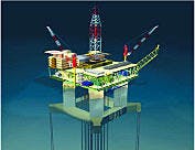
The ETLP (Fig. 3) will be installed in 3,863 ft of water in Angola's Block 15 and will be the first floating dry-tree unit to operate off West Africa. Operator of the development is Esso Exploration Angola (Block 15) Ltd., a subsidiary of ExxonMobil Corp.
ABB's other ETLP is slated for installation in 4,700 ft of water in the Gulf of Mexico.
New generation TLP
ABB for nearly 2 years has invested millions of dollars to develop the ETLP concept for a variety of topsides payloads, riser counts, water depths, and regions of the world. It has done extensive engineering, design, and physical model testing on the concept, which has been reviewed by the American Bureau of Shipping (ABS) and Det Norske Veritas (DNV). Both organizations have given it an "Approval in Principal" status.
A typical ETLP hull configuration consists of four vertical columns that can be square or cylindrical in cross section. Rectangular pontoons connect the columns below the water surface. On the top of the columns and integral to the hull is the structural deck that supports the topsides production facilities, drilling system, quarters, etc.
The primary difference between a conventional TLP and the ETLP is the hull form. Previous TLPs had tendons that were connected to the lower portion of the hull at the columns. On the ETLP, the columns have been moved inboard, allowing a more favorable support for the deck and its associated riser and drilling related loads. Pontoon extensions outboard of the columns provide the tendon connection points.
Fig. 4 illustrates the difference between the conventional TLP and ETLP hulls.
ETLP advantages
The ETLP's most distinctive features relate to weight savings and the efficiency of project execution. Compared to the conventional TLP, the ETLP has a 40% weight savings for the hull and deck steel.
The structural-weight-efficiency ratio indicates the ETLP's effectiveness to carry topsides payload. This ratio quantifies the payload weight that can be supported by a given weight of a hull and deck platform. For an ETLP the ratio is high and ranges from 0.8 in the Gulf of Mexico to 1.15 for West Africa.
Another ETLP advantage is that it can be installed as a completely integrated and commissioned unit. The shorter and less complex installation operation is less likely to be adversely affected by inclement weather. Installation of a completely integrated and commissioned unit is also more favorable for remote locations such as West Africa.
For developments requiring 10 or less production risers, an operator can install a three-column ETLP. This smaller version has undergone the same extensive development work as the four-column ETLP.
The ETLP when installed in conjunction with an FPSO allows the distance between the two vessels to be less than the distance between a dry-tree spar facility and FPSO. This shorter distance is due to the different mooring systems used on a spar and ETLP.
The closer distance between vessels alleviates flow assurance issues and lessens fluid transfer line loads.
Applications
From an economic standpoint, the optimal selection of a deepwater hull form depends on water depth, topsides payload, and design environment.
The associated tendon mooring costs of a TLP in deep water are high, although the improved motions of a TLP-type structure are more desirable for drilling and production operations. Other floating-type platforms are generally more applicable for heavier payloads in greater water depths. ABB currently is doing additional development work to extend the water depth and payload range of the ETLP.
Based on ABB's extensive analysis and evaluation, Fig. 5 illustrates the water depths, payloads, and metocean conditions in which the ETLP is an economic option. One can install ETLPs in deeper water if the topsides payloads are small and the environment is more benign, such as off West Africa.
West Africa environment
Wind, waves, and current are the fundamental elements that characterize metocean conditions. The source and intensity of these elements off West Africa is different than in the Gulf of Mexico.
Off West Africa trade winds are almost constant year-round and have a low intensity. This region does not have hurricanes and the most significant wind events are squalls. Because of the nature of these storms, one must treat them in a transient manner to properly capture their true effect on an offshore facility.
Swells rather than local waves generated from the relatively mild trade winds dominate the wave environment off West Africa. Large swell events are typically noncollinear with local wind because swells are generally a byproduct of distant storms. The ETLP's low natural periods of heave, roll, and pitch prevent amplification of these movements with the long swell periods.
Normal currents off West Africa are generally mild and nearly constant year-round. For example, off Angola, the more significant current event corresponds to wind-driven fresh water discharged from the Congo River.
ETLP design
Platform offset is the primary quasistatic response parameter that drives the ETLP design (Fig. 6). Offset and the associated setdown of the platform result from steady wind and current loading and can have the largest impact on design criteria such as still-water air gap and tendon pretension.
The platform's dynamic response to waves and its potential affect on the strength and fatigue behavior of the tendon system is another very important design parameter.
The benign West Africa metocean conditions on the design of the ETLP have a significant effect. For example, the system has less offset because wind and current loading on the ETLP are much lower than in the Gulf of Mexico. Typical TLP offset in the Gulf of Mexico is about 10% of water depth, while ETLP offsets off West Africa are about 4%.
Unlike the Gulf of Mexico, the ETLP design allows it to be fully operational during 100-year conditions off West Africa.
This smaller offset coupled with the low wave environment permits the ETLP to have a reduced still-water air gap. Less wave action off West Africa also allows the ETLP to have a smaller draft. The net affect is that an ETLP has a shorter column height.
Another factor unique to West Africa is pontoon size. To enable the fully integrated ETLP to float on and off of a dry transport vessel, the pontoons must have a large cross-section to obtain the necessary buoyancy. Normally, large pontoons will attract greater wave loading that will increase dynamic tendon tensions. Off West Africa, however, the low wave environment prevents this from happening.
By examining the components of total tendon tension, one can notice the differences between West Africa and Gulf of Mexico metocean conditions. Three components of total tendon tension and their typical contribution to the total are as follows:
These percentages indicate that the West Africa metocean conditions lack a high dynamic component, with the pretension component being the largest contributor to tendon tension. This allows the ETLP with its low offset to be fully operable during extreme metocean conditions.
Fig. 7 compares the steel weights between the ETLP designs for West Africa and Gulf of Mexico. Water depth for all cases is 3,000 ft, and payload is the sum of the platform's facilities weight in the operating condition, operational rig weight, steel-catenary-riser (SCR) top tensions, and production riser top tensions. This payload definition does not include deck steel weight.
The figure also shows a curve representing actual conventional TLP designs in the Gulf of Mexico.
The difference in these curves indicates that total steel weight (sum of hull, deck, and tendon steel) for an ETLP in the Gulf of Mexico compared to a conventional TLP is about 17% less for a payload of 15,000 tons.
For the same water depth and payload conditions, an ETLP in West Africa will realize a total steel weight saving of 38% over a similar ETLP in the Gulf of Mexico.
A downsized ETLP off West Africa also allows for a broader range of applications. Specifically, one can install the ETLP in deeper water with heavier topsides payloads. For example, an ETLP designed for a 13,000 ton payload in 3,000 ft of water in the Gulf of Mexico can be extended to a water depth of 5,800 ft off West Africa. Water depths exceeding 6,000 ft are possible with lighter topsides payloads.
Also, changes in hull form and tendon design may allow even greater water depths.
ETLP installation
High safety, low risk, and minimal offshore exposure time during installation are key elements for successfully installing facilities off West Africa.
One critical element in the delivery process of an ETLP is the use of temporary stability modules (TSM). Operators can realize cost and schedule savings when the deck and the hull integration is done at quayside rather than offshore. This especially is true for a remote area such as West Africa.
The addition of the TSMs to the ETLP allows for a safe and low risk installation aid. These modules provide the necessary water plane area to ensure a stable vessel during all preservice phases from integration to platform installation.
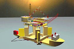
Fig. 8 shows the TSMs in their installed position during dry transport of the fully integrated ETLP to site. One removes the TSMs after installation of the ETLP because stability of the unit is no longer an issue.
The TSMs contain compartments and exceed all regulatory requirements for damage control. The ETLP requires four TSMs, one connected on each column.
The hull fabrication yard installs the TSMs on the ETLP hull prior to deck integration. The TSMs also have a simple ballast system that uses the hull's pumps to fill the TSMs during ETLP installation.
The installation requires significant ballast water to achieve the draft necessary for tendon hookup. The additional compartments in the TSMs eliminate the need for temporary ballast tanks within the hull.
A system of shear blocks attached to the ETLP hull positively restrains the TSMs. The shear blocks provide a reliable passive system and are sized to transfer, in an efficient manner, all operational loads from the TSM to the ETLP hull.
The block design also allows a crane vessel, already on site, to easily remove the TSM after completing the ETLP installation. To further ensure safety, the removal process does not required personnel to be near the TSM during lifting operations.
The author
John W. Chianis is vice-president and general manager of ABB Lummus Global - Deepwater Systems Division, Houston. He worked on his first TLP project in 1978, and since then, he has participated in a large number of TLP conceptual studies and designs. Chianis holds BS and MS degrees in ocean engineering.


