High-strength lightweight blend improves deepwater cementing
Successful cement jobs, providing good zonal isolation and adequate casing and wellhead support, become difficult goals to achieve at water depths grea ter than 2,000 m.
Operators must overcome several challenges:
- Ultralow cementing temperatures have a major adverse impact on compressive strength development and require special cementing design parameters.
- Low fracture gradients require slurry density reduction to allow for adequate annular fill-up.
- Large hole and casing diameters require bulk management and mixing considerations.
- Optimizing downhole hydraulics requires job design simulations.
- Minimizing nonproductive rig time requires operational planning and efficient job execution.
Because of the enormous drilling costs associated with deepwater projects, solutions to optimize casing support and subsea wellhead stability also become major challenges.
The case histories of two exploration wells drilled in an ultradeepwater area off Brazil, at water depths greater than 2,000 m, highlight methods the operator used to meet the challenges.
A specialized cementing system such as high-strength, lightweight (HSLW) cement combined with a sandwich cementing system has allowed the operator to optimize economics.
The HSLW blend provides support at key low-temperature sections such as at the wellhead and shoe track, while the gel-extended cement slurries provide adequate isolation and support in the less critical annular sections.
Operators should follow good cementing practices during all cementing operations. Operations and technical personnel should provide rigorous plan ning and laboratory testing to maximize slurry designs.
Operators must use temperature simulations to better predict downhole temperature effects from the seawater column for optimizing thickening-time testing and for evaluating cement compressive-strength development.
Slurry-density formulations and pumping rates must agree with predicted safe fracture-gradient analysis.
Campos basin
As operators pursue offshore oil and gas exploration in deeper water-and as rigs capable of drilling these wells command high operating rates-minimizing wait-on-cement time (WOC) can provide substantial savings.
The Campos basin, offshore Brazil, is a prolific deepwater basin with extensive oil and gas development in water depths of 600-2,000 m.
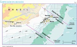
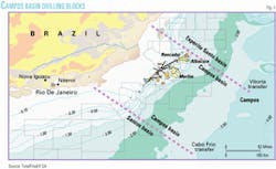
As seen in some of the basin's new drilling blocks (Fig. 1), water depths approach 2,500 m and seabed temperatures can drop to as low as 3-4° C.
These conditions require a specialized slurry design with low density and high early compressive strength to minimize WOC time and provide enough support for the wellhead and casing string architecture.
Operators have reported some major operational problems where the wellhead housing at the seafloor has dropped as much as 3-5 m.
In some cases, the housing was completely lost, requiring a new well to be drilled.
Normal operational difficulties become serious challenges in deep water.
They include: maintaining circulation while conditioning or cementing the wellbore, displacing annular geometries with potential washouts exceeding 100%, and providing a competent cement sheath with early compressive strength buildup to support the wellhead casing at the seafloor.
Deepwater cementing
Successful deepwater cementing depends on well architecture, temperature profile, pore pressure and fracture gradient, displacement mechanics, and cement volume determination.
Well architecture
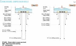
Fig. 2 shows the casing designs for two Campos basin wells with standard deepwater configurations. The rig had jetted the 36-in. surface casing into place with bentonite mud sweep pills.
The operator had run and cemented the 20-in. conductor casing to about the same depth in both wells. Well 1, however, had a 30-in. wellbore rather than 26 in., which increased the volumes and complicate the job logistics.
After installing the blowout preventer (BOP) and riser, the rig drilled the 171/2-in. hole with 1.08 sp gr KCl polymer mud. Crews then ran the 133/8-in. casing, which was cemented to about 100 m inside the 20-in. casing.
After drilling the 121/4-in. hole section with 1.11 sp gr KCl polymer mud, crews ran the 103/4 x 95/8-in. casing and cemented it to 150 m inside the 133/8-in. casing.
Temperature profile
Water depth and the resulting temperature profile is one of the main design considerations for offshore cementing operations.
API tables provide calculations for normal cementing conditions with vertical wellbore geometry, but current API tables and procedures do not address the temperature needs of ultradeepwater cementing.1
The resulting practice has been for the industry to use data gathered from downhole temperature devices in wellbore temperature simulation software to predict bottomhole circulating temperatures (BHCT). However, the cooling effects associated with the seabed conditions tend to complicate the simulation because it is difficult to determine rates for cool-down and heat-up.
The cement hydration rate-of-reaction depends on the temperature environment and will decrease as the temperature decreases.
Decreasing temperatures negatively influence compressive strength development, meaning that it takes longer for adequate compressive strength to develop.
Work performed with large-scale models and temperature simulators also has provided valuable information for determining curing temperatures, supplementing bottomhole static temperature (BHST).
One group has proposed a method that uses a simulated slurry temperature (SST), which is a curing temperature profile rather than a single static temperature.2
The SST is more representative of the actual cement slurry curing conditions and has a positive impact on the WOC time.
With WOC time vs. rig cost a major consideration and seabed casing support mandatory for drilling operations to continue, a slurry design with rapid compressive strength development becomes extremely important.
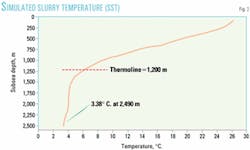
Water and seafloor temperatures become the basis for slurry design optimization and laboratory testing (Fig. 3).
Pore, fracture pressure
Seabed and near-seabed formations tend to be loose and poorly consolidated.3 These weak zones are susceptible to damage from drilling operations, as there is normally a narrow margin between the pore pressure and fracture gradient. Because of this narrow margin, high flow rates or excessive rheology in low-temperature conditions can wash out the wellbore or fracture the formation. Thus, hole cleaning becomes complicated during drilling and while cementing the large casing into the wellbore.
Normal density slurries (1.9 sp gr) tend to initiate fractures, which can induce circulation losses; thus, low-density slurry designs (1.4-1.5 sp gr) are more successful for maintaining good circulation to the seafloor wellhead equipment.
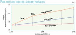
When losses occur, unscheduled top jobs may be required, costing valuable rig time. Fig. 4 represents a pore-pressure and fracture-gradient prognosis.
Displacement mechanics
The displacement process is important for any cementing job. In the deepwater environment, many of the key factors in the displacement process are difficult to apply. These factors include: conditioning of the drilling fluid, using spacers and flushes, pipe movement, centralization, and optimizing displacement rates.
Rigs normally drill the top-hole section without the use of a riser, so all returns deposit at the seabed. This, in combination with the low fracture gradients, discourages conditioning of the wellbore before cementing operations begin.
Because of the large pipe and hole configuration, high annular velocities to promote good displacement are impossible. This lack of velocity makes it difficult to effectively remove all residual drilling mud and cuttings.
Even though pipe movement is very effective for mud removal, many drilling engineers consider it too great a risk and seldom consider its use. Only one deepwater prospect has documented the use of pipe movement for improving the cementing process.4
Mud conditioning, optimized flow rates, and centralization are keys for efficient hole cleaning and cement placement.5-7
Cement volume
When cementing the structural casing (more commonly referred to as conductor casing), operators must circulate an adequate volume of quality cement slurry back to the seafloor to ensure proper wellhead support.
In some cases, slurry volume excess due to hole washout may reach as much as 300-400%.8 This results in large volumes of slurry being required to fill the annulus.
These large cement volumes may create other problems, such as inadequate bulk cement-blend storage and mixing fluid-tank capacities. Job execution and overall operations become difficult when cement volumes approach 200 cu m.
Job design
Key parameters for designing a cement job in deepwater environments include temperature simulation, along with pore pressure and fracture gradient prediction. When these parameters have been defined, technicians can prepare a cement slurry design and formulation and properly simulate the job to satisfy well conditions.
Temperature simulation
Operators can use data from drilling and evaluation instruments to estimate the temperature conditions for cement testing; however, they should run simulations to determine accurate cementing temperature profiles.
For deepwater projects, the HPHT consistometer used for thickening-time (TT) tests must be equipped with a cooling apparatus to regulate the temperatures below room temperature.
Technicians should duplicate downhole conditions as closely as possible to optimize field conditions. In addition, they can determine SST used for compressive strength testing from a temperature simulation.2
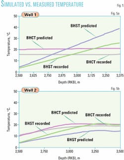
Figs. 5a and 5b compare predicted and recorded temperatures from instruments used to measure circulating temperatures while drilling (MWD) and static temperatures (logs). Based on these data, existing software can perform a better cementing temperature simulation.
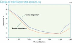
Fig. 6 represents the temperature curve included on the 20-in. casing job simulation to evaluate downhole rheologies and corresponding friction pressures.
Expected gradients
As previously discussed, formation integrity near the seafloor is normally low, with poorly consolidated sands. In some cases, there may exist water flows that further complicate the drilling and cementing operations.
When planning for an exploration well, engineers take data from the nearest offsets for well design. Fig. 4 shows data for the anticipated pore pressures, mud weight, and fracture gradients expected in the Campos basin.
As can be seen from the data, the wells require a low-density cementing system to ensure good cement fill-up back to the seabed and eliminate any potential fractures into the formation.
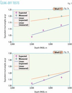
In addition, Figs. 7a and 7b show the difficult match between the expected fracture pressures given in Fig. 4 and the results from the leak-off tests (LOT) performed on both wells.
Slurry design
Based on the above conditions and requirements, it is obvious that the exploration wells require a specialized cementing system.
This system, designed at lower-than-standard density, but capable of high early compressive-strength development in a low-temperature environment, is equivalent to properties that an HSLW blend delivers.
Composition
The basic components are Class G cement blended with microelements to enhance slurry performance at low density and promote early strength at low temperatures.
One of the microelements has a pressure-dependent den sity, which explains the different surface and downhole densities one obtains while using this type of blend.
Although other density ranges are possible, engineers designed this blend to be mixed at 1.4-1.5 sp gr to satisfy circulating density limits.
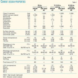
The blend also requires laboratory testing to determine acceptable concentration of the traditional additives, such as accelerators, retarders, free water, and fluid loss control. Table 1 shows the slurries and their properties used in this project.
An important factor in choosing this type of slurry was the absence in this region of shallow water or gas flows that are so common in the Gulf of Mexico and other parts of the world. If the engineers had suspected shallow hazards (below the mud line), they would have proposed another slurry, such as high-performance foamed cement.
The HSLW blend has obvious advantages over standard gel slurries. However, in large-volume jobs needed for deepwater surface pipes, it requires above-average bulk storage capacity that can result in logistical problems.
In these lightweight slurries, inert dry-blended materials replace the extra amount of water, which allows them to have such good compressive strength properties. For example, in the case of the two slurries used to cement the 20-in. casing strings, for 1 ton of bulk material, the downhole yield for the HSLW blend slurry is 30% lower than the yield for the gel slurry.
In addition, 1 ton of HSLW blend occupies more than double the bulk volume of standard cement, so using HSLW blends requires nearly three times the bulk storage of standard Class G cement in gel slurries.
For this reason, the operator used both systems in this project, with the HSLW blend used for zonal isolation at the critical points such as the seafloor wellhead housing and at the casing shoes.
Engineers added the gel-extended system as economical filler slurry to provide adequate support and isolation through the less-critical sections of the casing and wellbore.
The thickening times for gel-extended slurries are usually much longer than required, even with introduction of accelerators such as seawater and calcium chloride. Thus, early and extended compressive-strength development is quite low when compared to the HSLW blend.
Engineers considered the compatibility of the interface between the slurries to confirm that the system was rheologically and density balanced to minimize fluid bypass.
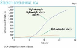
Technicians analyzed the base slurries for strength development with an ultrasonic cement analyzer (UCA). The UCA indicates the compressive strength development in a cement sample that is cured under downhole temperature and pressure conditions.9
The UCA measures the strength development by the change in velocity of the ultrasonic signal transmitted through the subject sample as it hardens. Fig. 8 shows the UCA chart, with Table 1 providing additional properties.
Job simulation
Computer simulations analyzed wellbore temperatures, fluid volumes, and equivalent circulation density (ECD) profiles.
Cement job designers should calculate the ECD, corresponding to the hydrostatic pressure (static condition) plus friction pressure (dynamic condition), based on well architecture, fluids rheological properties given the temperature profile, and pumping rate.10
Technicians can adjust fluid rheologies and optimize flow rates from these simulations for better mud removal while remaining below critical fracture gradients.
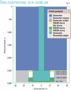
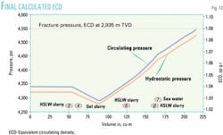
For example, Figs. 9 and 10 show two graphs related to the 20-in. casing job in Well 1. Fig. 9 shows the final fluid positions, while Fig. 10 shows the final calculated ECD during the job, using actual parameters.
The graphs demonstrate that a displacement rate of 3,000 l./min (actual rate) was possible without exceeding the critical fracture gradient.
Although they were not used on these wells, the computer programs in this simulation can also capture real-time data that can be used on location for comparing planned job performance to the actual conditions. Rig-based personnel can also transmit the data to land-based offices or alternate locations.
Field execution
The following describes the large diameter (20 in. and 133/8 in.) casing jobs, which used the HSLW blend.
20-in. casing
When the 36-in. jetting operation had been completed, the rig drilled the 26-in. hole section with seawater and high-viscosity sweeps. It then spotted high-viscosity mud (1.17 sp gr) in the hole section for wellbore stability before tripping out-of-hole to run casing.
Crews then ran the 20-in. casing with the wellhead assembly, using a 65/8-in. drillstring. The rig coupled a 5-in. cementing stinger assembly at the end of the 65/8-in. drill pipe and positioned it 44 m from the 20-in. shoe.
This configuration allowed for better cement placement and sufficient distance to safely clear the drill pipe without over-displacing the cement occupying the shoe track.
The cement jobs employed a sandwich sequence with gel slurry in the middle and HSLW slurries at the top and bottom. The job design placed the initial HSLW slurry up to the mud line or seabed, the gel slurry as filler was left to cement the middle of the casing string, and the same HSLW slurry was left at the casing shoe.
The jobs followed the sequence below, with the volumes shown relating to Well 1, which had the larger 30-in. hole, rather than Well 2 with the smaller-volume 26-in. hole.
- 50 cu m seawater spacer, containing a fluorescent dye tracer for observing returns at the sea floor.
- 20 cu m HSLW slurry (1.42 sp gr on surface for 1.52 sp gr downhole), to be placed at the casing and wellhead housing.
- 130 cu m gel-extended slurry (1.54 sp gr), assuming 100% excess to be placed in the annulus from the 36-in. shoe depth to 150 m above the 20-in. shoe track.
- 56 cu m HSLW slurry (1.42 sp gr on surface for 1.52 sp gr downhole) to provide support and superior zonal isolation around the shoe track.
Crews used seawater for displacement at a flow rate of 3,000 l./min to position the slurries at the proper place in the annulus and shoe track (Fig. 9).
The job design based the ECD on data from Fig. 4 and required that this value not exceed 1.09 sp gr during cement placement (Fig. 10).
A chemical-metering system injected the liquid additives directly into the mixing tub, allowing more uniform additive proportioning and less waste from large tank "dead" volumes.
13 3/8-in. casing
After running the BOP stack and riser, the rig drilled the 171/2-in. hole with KCl polymer mud (1.08 sp gr). Crews then ran the 133/8-in. casing with a 65/8-in. drill pipe landing string and only the top-cementing plug attached.
In water depths below 2,000 m with landing string volume higher than the requested spacer volume, crews displace the cement slurry with only a dart sub and top plug, which minimizes the risk of the landing string filling with cement if the bottom plug is not released.
The job followed the sequence below, with the volumes shown relating to Well 2, since no gel-extended slurry was pumped in Well 1.
- 20 cu m flush.
- 40 cu m gel extended slurry, assuming 100% excess to be placed in the annulus from 36-in. shoe depth to 150 m above the 20-in. shoe track.
- 45 cu m HSLW slurry (1.39 sp gr on surface for 1.50 sp gr downhole).
The rig used seawater for displacement at a flow rate of 2,500 l./min to position the slurries at the proper place in the annulus and shoe track.
Postjob analysis
Figs. 5a and 5b compare measured vs. simulated temperatures in Wells 1 and 2, with BHSTs calculated from logs and BHCTs measured by an MWD probe. As the graphs indicate, recorded and simulated circulating temperatures match very closely, even though the static temperatures do not match as well.
Figs. 7a and 7b show the leak-off tests obtained vs. those expected on both wells, with the measured LOTs being greater than expected.
Considering the constraints of adequate rig bulk storage, as well as the economical impact of using one special blend, the sandwich process satisfied all well-cementing parameters in the 20-in. casing job.
The relatively high viscosity of the HSLW slurry, also matched by the gel slurry viscosity, provided better mud displacement in the large casing-hole annuli. It was imperative that both slurries have similar viscosities to ensure displacement and avoid intermixing.
Some lessons learned from the operation pertain to the bulk transfer of the HSLW blend. Some attention must be given to the bulk transfer because of the inherent nature of special blends and the different densities of individual components.
During the first job, which was the 20-in. casing in Well 1, logistics caused the HSLW blend to be placed in bulk silos quite far from the mixing unit. Operations personnel have minimized some of the bulk transfer difficulties by the following:
- The rig placed the blend as close as possible to the mixing unit. Lessening the distance required to transfer bulk blend to the mixing system improves overall operation.
- Less than 24 hr before the job, operational personnel fluffed the blend with air pressure for 12 hr for homogenization.
With these procedures, the mixing rate was improved and remained constant. The use of bulk-flow enhancers could further improve bulk transfer.
Acknowledgments
The authors thank TotalFinaElf and Halliburton Energy Services Inc. management for their support in preparation and publication of this article.
References
- API Recommended Practice for Testing Oil Well Cements, API Recommended Practice 10B, 22nd Edition, December 1997.
- Ravi, K., et al., " Deepwater Cementing Challenges," SPE 56534, presented at the SPE Annual Technical Conference and Exhibition, Houston, Oct. 3-6, 1999.
- Simmons, E.L., and Rau, W.E., "Predicting Deepwater Fracture Pressures: A Proposal," SPE 18025, October 1988.
- Young, W.S., May, B.C., and Varnado, B.R., "Genesis Development Project Overview," OTC 10796, presented at the Offshore Technology Conference, May 1999.
- Smith, T.R., and Ravi, K.M., "Investigation of Drilling Fluid Properties to Maximize Cement Displacement Efficiency," SPE 22775, presented at the SPE Annual Technical Conference and Exhibition, October 1991.
- Haut, R.C., and Crook, R.J., "Primary Cementing: The Mud Displacement Process," SPE 8253, presented at the SPE Annual Technical Conference and Exhibition, Las Vegas, Sept. 23-26, 1979.
- Beirute, R.M., Sabins, F.L., and Ravi, K.M., "Large-Scale Experiments Show Proper Hole Conditioning: A Critical Requirement for Successful Cementing Operations," SPE 22774, presented at the SPE Annual Technical Conference and Exhibition, October 1991.
- Piot, B., et al., "West Africa Deepwater Wells Benefit from Low-Temperature Cements," SPE/IADC 67774, presented at the SPE Drilling Conference, Amsterdam, February 2001.
- Burkhalter, J.F., Sutton, D.L., Rao, P.P., Sabins, F.L., "A Laboratory Instrument to Continuously Monitor the Compressive Strength of Cement Slurries," presented at the Southwestern Petroleum Short Course, Lubbock, Tex., April 1984.
- North, J., Brangetto, M.P., and Gray, E., "Central Graben Extreme Offshore High-Pressure/High Temperature Cementing Case Study," SPE/IADC 59169, presented at the SPE Drilling Conference, New Orleans, Feb. 23-25, 2000.
The authors
George Fuller is cementing account representative for Halliburton Energy Services in Rio de Janeiro, Brazil. Previously he worked in various engineering positions with cementing operations in the Gulf of Mexico and in other Latin American Countries. He recently co-authored technical papers on foamed cementing operations performed in the southern cone of Latin America. He joined Halliburton in 1977 after receiving a BS in Electrical Engineering from McNeese State University. He also has an MS in engineering management from the University of Southwestern Louisiana and is a petroleum engineer registered in Louisiana.
Paulo Roberto Souza is a mechanical engineer for Halliburton Energy Services. He joined Halliburton Brazil in 1982 and has worked onshore and offshore on cementing, stimulation, and sand control services. He spent 3 years in Mexico working in the Gulf of Mexico on carbonate stimulations. He has a BS in mechanical engineering from Pontifícia Universidade Católica de Minas Gerais.
Luis Ferreira is the global account technical advisor for Halliburton Energy Services near TotalFinaElf technical center in Pau, France. Before his current position he spent 2 years as cementing regional advisor at Halliburton Research Center in Holland. He joined Halliburton in 1980 and served as field engineer in several western Africa countries and later as operations manager in France. He has an MS in engineering from IST University in Lisbon.
Daniel Rouat works for TotalFinaElf SA and is in charge of mud, cementing, and environmental issues related to deepwater and complex wells. He worked as a mud engineer and superintendent for various services companies from 1977 to 1991. He then joined Elf Aquitaine as fluids superintendent and later became a fluids specialist in the well engineering construction team in TotalFinaElf's main office. He has a BS in chemical engineering from the University of St Nazaire in France.
