Adjustable-gauge stabilizer in motor provides greater inclination control
Placement of an adjustable-gauge stabilizer within the bearing housing of a steerable motor avoids problems encountered by stabilizers located above or below the motor.
In this near-bit position, changes in a stabilizer's gauge have a greater effect on wellbore inclination. Also, this placement decreases stresses on the motor.
This type of adjustable-gauge motor has been run in long horizontal sections in the Middle East and has improved overall drilling rates when compared with conventional steerable motor runs.
Drilling tools
The industry has a wide range of tools for drilling increasingly complex and expensive wells. Long horizontal sections can be drilled with anything from a simple rotary assembly to the latest generation of rotary steerable systems, depending on the complexity of the well design.
Generally in high-angle wellbore zones, the main objective is to control the wellbore inclination in response to changes in the reservoir geology. In certain reservoirs that exhibit lateral variations in porosity and permeability, however, it may be necessary to maintain a control of wellbore direction. Although this can be done with conventional steerable assemblies, the assemblies may cause problems that result in high induced doglegs and poor hole cleaning when drilling in a sliding mode.

A drilling assembly for these wells, therefore, is required that maximizes control of inclination in the rotary mode, retains some ability to control azimuth, minimizes induced doglegs, and does not require expensive 3D rotary steerable systems.
Controlling inclination
In directional drilling, drillers generally control wellbore inclination by making changes in the bottomhole assembly or using a steerable motor.
Changes in the bottomhole assembly require time-consuming trips, and steerable motors, which require slide or oriented drilling, substantially reduce rate-of-penetration (ROP), and increase torque and drag.
Sliding also can result in poor hole cleaning and potential sticking problems.
In the late 1980s, the industry developed new stabilizers whose effective blade OD could be changed while the tool was downhole. With these adjustable-gauge stabilizers, the driller could change stabilizer OD without having to make time-consuming and costly trips out of the hole.
The gauge adjustments downhole also provided less abrupt inclination changes than those caused by a motor alone. This resulted in smoother wellbores.
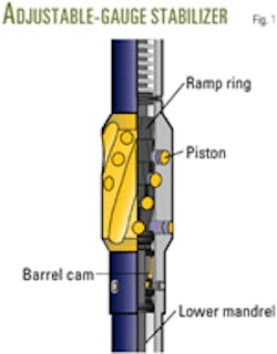
Various stabilizers became available. One design used mud flow rate to signal the tool to change its diameter. Buttons in the stabilizer blade moved in or out every time the tool recognized circulation. This simple mechanism was easy to control and resulted in a rugged and reliable tool (Fig 1). A shift in the standpipe pressure base line level indicated whether the buttons were extended or retracted.
Adjustable stabilizers run in rotary drilling assemblies often were placed near the bit or positioned about 15-30 ft from the bit. In these positions, changes in their gauge could effectively control the build or drop tendency of the assembly.
Because they controlled inclination while in the rotary mode, these assemblies became known as 2D rotary systems. This designation indicated that one could not effectively control the wellbore direction or azimuth in the rotary mode.
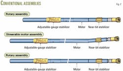
Adjustable stabilizers could also be run with steerable mud-motor systems. Placement of the adjustable stabilizer above the motor made it possible to control inclination with the stabilizer while drilling in the rotary mode. If the wellbore required a change in azimuth, one would have to revert to a sliding mode (Fig 2).
With this assembly, it seemed at first that both inclination and azimuth could be controlled without too many compromises.
2D rotary limitations
Limitations of the 2D system became evident during drilling. The system required the adjustable stabilizer to be above the motor, about 30 ft from the bit. In this position, changes in the stabilizer OD are relatively limited to doglegs of only 0.5-1°/100 ft, depending on tool and hole sizes.
For 6-in. holes, the motor may be too limber so that the effect of stabilizer gauge changes on inclination can be almost zero. This may be fine for situations in which one only requires limited control of inclination; however, in other situations requiring more rapid change in inclination, one may be forced to resort to steerable motor and slide drilling that could cause problems.
The industry now commonly drills horizontal sections with a geological steering or pay-zone steering device that usually consists of a logging-while-drilling (LWD) tool with a resistivity sensor. A resistivity sensor, with its deep investigation depth, can detect a geologic change many feet before the bit penetrates that boundary. This ability may allow one to hold the drilling assembly in the reservoir by steering it with a conventional steerable motor and adjustable stabilizer away from either an upper or lower boundary.
In certain reservoirs, however, a resistivity sensor cannot be used for geological steering. In these cases, one must use a gamma ray or formation porosity sensor. Because of their shallower depths of investigation, these tools may only detect the boundary at about the time the bit is already at a boundary. In this case, one has to quickly change the wellbore path to remain within the pay zone.
With a steerable assembly, the driller must revert to slide drilling to change the path, but his first problem may be a loss in the ability to slide because of excessive torque and drag having built up in the wellbore.
If an adjustable stabilizer is above the motor, he might be able to change the gauge and make a slow correction of the path back into the reservoir. This correction, however, may be so slow that possibly hundreds of feet of pay zone are missed before the wellbore re-enters the pay zone.
Drilling in the sliding mode is slower than rotary drilling so that such a correction run may, depending on the exact circumstances, take more time to drill. In addition, hole cleaning while sliding in the horizontal section may become a problem.
The dogleg introduced by using the motor to control inclination, if repeated, may result in additional torque and drag that could possibly prevent the horizontal section from reaching its planned TD.
The industry, therefore, needed a drilling system that allowed sufficient control of inclination for pay-zone steering purposes while remaining in the rotary mode.
Motor with stabilizer
The main problem of a conventional adjustable stabilizer-steerable motor assembly is that the stabilizer is too far from the bit.
One solution has been the placement of the adjustable stabilizer between the motor.
This has been tried with a certain degree of success.1 But in this configuration, stresses on both stabilizer and motor have caused reliability problems in both systems.
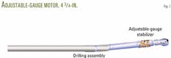
A more recent solution is the adjustable-gauge motor with an adjustable-gauge stabilizer built into the motor just above the bearing housing (Fig 3). In this configuration, the stabilizer is about 10 ft from the bit, and changes in blade diameter have more effect on inclination changes.
In addition, the assembly allows a bend to be set in the motor's adjustable housing.
Although the maximum bend allowed might be less than in a conventional steerable motor, it will still be sufficient to allow orientated drilling.
Placement of the adjustable stabilizer above the motor's bearing housing also means that the mechanical reliability of both the motor and stabilizer are not compromised.
The adjustable-gauge motor, therefore, is as reliable as a standard motor.
Case histories
Dubai Petroleum Co. has drilled in the Arabian Gulf since the 1960s and started drilling horizontal wells in the early 1990s.
Its newer wells have become increasingly complex, with primary issues being the proximity to offset wells and wellbore placement. Of increasing concern also has been the amount of time spent in the orientated drilling mode that is required for rapid changes in true vertical depth (TVD) or azimuth.
Orientated drilling has the potential to cause drilling assemblies to become differentially stuck, reduce overall rateof-penetration, and increase torque and drag. Dubai Petroleum, therefore, ran the adjustable-gauge motor to try and maximize rotary drilling time while providing some degree of steerability.
It selected a 43/4-in. adjustable-gauge motor because of the 61/8-in. hole being drilled.
In the 61/8-in. holes, Dubai Petroleum ran the stabilizer with a 6-in. diameter for the extended position and a 51/2 -in. diameter for the retracted position. A standard 4:5 lobe power section motor section and tri-cone, insert bits was used because the formation's drilling characteristics were well known. The bend in the motor's adjustable housing was set to 0.75°.
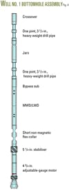
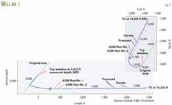
In the first well, the bottomhole assembly (Fig. 4) tripped in freely. Because Dubai Petroleum did not have experience with the adjustable-gauge motor, it decided to drill 50 ft with the adjustable stabilizer set in the 6-in. full- gauge position. This would be followed by a further 50 ft with the stabilizer in the flush position or in the 51/2 in. undergauge mode to try and establish the directional tendencies of the assembly.
After the assembly broke over the relative build or drop trends of the previously drilled wellbore, the driller initially found the assembly to be very responsive, performing closely to modeled calculations. The assembly built about 2.5°/100 ft in full gauge and dropped about 3.0°/100 ft when in the undergauge position.
Based on these results, the driller geologically steered the well path in the rotary mode and raised the TVD by 30 ft, at which point, he reduced the inclination to 90° and maintained this depth as the TVD.
The rate-of-penetration of this 2,200-ft run was a record for this field. This rate was possible primarily because of the ability to remain in rotary drilling mode, because the operation was only concerned with TVD control. The record indicates that eliminating slide-oriented drilling saves time.
The adjustable-gauge motor operated flawlessly throughout the run. The difference in standard pipe pressure signal between the undergauge and full-gauge positions remained at about 300 psi and was clearly visible at surface.
The tool's response varied but this was attributed to formation anomalies and not its mechanical properties.
It should be noted that in Well 1 there was a known tendency for the bit to walk to the right; therefore, the walk seen with the adjustable-gauge motor also was judged to be solely due to the formation.
In the second well, the adjustable-gauge motor tripped in without difficulty and drilled 2,500 ft of lateral to TD. Penetration rates varied from 100 to 200 ft/hr with 6,000-10,000 weight on bit.
In this well, the adjustable-gauge motor provided good control with a 0.5-1.5°/100 ft build in the extended 6-in. gauge position and a 2-3°/100 ft drop in the 51/2-in. flush gauge position.
The driller slid the assembly twice for a total 79 ft, with the 0.75° fixed bend providing an average dogleg severity of 3°/100 ft. Over the first 1,000 ft, the assembly walked left at 0.14°/100 ft. This azimuth was corrected with a 50-ft slide.
The assembly then walked right at 0.08°/100 ft over the remaining section to TD.
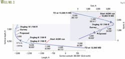
In the third well, the bottomhole assembly had to be washed down in the last 100 ft to relog and survey. Also the well path had to be steered 3.5° to the left to hit the target at TD because of an azimuth change from the previous survey tool.
The driller slid the adjustable-gauge motor for 103 ft, giving a dogleg severity of about 3°/100 ft. He then rotated the assembly for the remaining 2,000 ft to TD. Average penetration rate was 84.8 ft/hr.
The tool cycled every time with a pressure signal difference of about 400 psi and provided an average build rate of 1.6°/100 ft in the extended 6-in. gauge position and a average drop rate of 1.6°/100 ft in the 51/2-in. undergauge position.
Directional response was immediate with every gauge change. After the initial slide, the hole direction walked left at a rate of 0.4°/100 ft over the first 830 ft, but then averaged 0.2°/100 ft to the right over the remaining section. Drilling to TD, therefore, did not require any sliding.
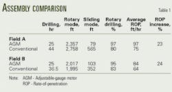
These and other case histories show that the amount of time spent in the sliding mode was significantly reduced and overall rate-of-penetration increased by 24% (Table 1).
Tool uses
The adjustable-gauge motor does have limitations; therefore, its benefits can best be realized in the following circumstances:
- In wells with straight paths in which one expects a minimal number of azimuth changes.
- In situations in which one expects to need rapid and relatively large changes in the TVD of a horizontal lateral.
- In any situation in which one requires larger changes between settings than provided by a standard motor and adjustable-gauge stabilizer bottomhole assembly.
- In 6-in. hole sizes in which one expects that an adjustable stabilizer above a motor will have little or no effect.
Currently available on the tool is a sensor, installed in the motor housing, that measures inclination nearer to the bit than conventional measurement-while-drilling (MWD) sensors. This sensor helps optimize geological steering applications.
Future developments of the adjustable gauge motor include development of larger sizes for 81/2 and 121/4-in. holes.
Acknowledgments
The authors thank Dubai Petroleum Co. for allowing publication of this article. Special thanks to Tom Gaynor of Sperry-Sun Drilling Services for help with the article.
Reference
- McMillin, K., "Techniques with adjustable gauge tools yield more directional control options," Offshore, February 2000.
The authors

Luke Lawrence is a staff drilling engineer for Conoco Inc., currently involved in Gulf of Mexico operations. He has 16 years industry experience, including the US and Middle East. Lawrence holds a BS in petroleum engineering from Montana Tech, Butte, Montana.

John Stymiest is directional drilling coordinator for Sperry-Sun Drilling Services, Dubai, UAE.. He has 25 years experience in the industry, with over 20 years in the field of directional drilling.

Richard Russell is business development manager for Sperry-Sun Drilling Services, Dubai, UAE. He has over 20 years of industry experience in the North Sea, West Africa, Far East, and Middle-East. Russell is a graduate of Reading University, UK.