Special Report: Leak-detection system designed to catch slow leaks in offshore Alaska line
Installation of the LEOS leak-detection system on the Northstar crude oil pipeline project in Alaska's Beaufort Sea was in response to a US Army Corp. of Engineers' requirement for a system to protect the subsea oil line against small, hard-to-detect leaks during winter months of continuous ice cover.
The system has been operating since Northstar began producing crude oil in October 2001.
Search for system
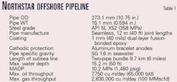
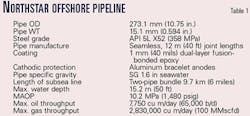
The Northstar development project is the first crude oil production facility constructed 10 km (6 miles) offshore in the Beaufort Sea (Fig. 1). The project signified the start of a new era in offshore crude oil production, extending the life of the Prudhoe Bay oil fields on the Alaskan North Slope.1
The project also imposed an even greater environmental responsibility on companies operating in the arctic environment. Partly in response to misgivings of environmental agencies that a small chronic subsea oil leak might exist undetected, the US Army Corps of Engineers stipulated that Northstar operator BP Exploration (Alaska) Inc. develop a prototype leak-detection system to be used on the pipeline in addition to two proposed state-of-the-art systems.2 3
At issue for the authorities was the ability of pressure and volumetric metering leak-detection systems to alarm when a very small leak exists in the line during flow. The pressure variations associated with a small leak can sometimes be masked by the "hydraulic noise" associated with upstream operations and pumping the crude oil through the line.
There was a concern that, if a small chronic leak were undetected during the winter months when the Beaufort Sea is ice covered, a significant volume of product could be lost. After research, the LEOS system was selected for this purpose. ("LEOS" is an acronym for the German "Leck Erkennungs Ortungs System" or "lead detection and location system.")
The LEOS system was originally developed 20 years ago for a pipeline project in Bavaria, Germany. The environmental conservation authorities were concerned about being able to detect a very small chronic leak in a gas ethylene feedstock pipeline installed under the Rhine River.
The solution was to install a leak detection system consisting of a small plastic tube alongside the pipeline through which air is periodically circulated.4 The tube is perforated and covered with a thin (1-mm) acetate outer layer that allows hydrocarbon molecules to diffuse through it and concentrate on the inside of the tube.
When the air is withdrawn during a sampling cycle, the hydrocarbon molecules move with the air current to an electronic sensing module. The air (with hydrocarbon molecules) passing through the module allows detection of the presence of the hydrocarbon.
In addition, the time taken for the sample to arrive at the measurement station is accurately gauged, thereby allowing the leak location to be determined.
The Northstar project evaluated many existing and developing leak-detection technologies because to select a system that could successfully operate in the arctic was important. The extreme temperature range experienced would severely test the installation and operation of the system.
The climatic variations from winter to summer were carefully evaluated because LEOS depends on continuous replenishment of the air inside the tube. In selecting a "prototype" leak detection system, the Northstar project team felt that, if possible, the technology should have an established track record.
LEOS provided several key advantages over other applied technologies, including:
- It provided the required leak-detection sensitivity.
- It provided leak-location capability.
- It is not prone to false alarms.
- It is a field-proven system.
- It has established an operating record longer than the design life of the Northstar field (22 years vs. 15).
- The vendor had considerable resources and expertise and was prepared to meet the exacting delivery schedule.
- The vendor was prepared to oversee and be responsible for installation and start-up.
Given the arctic location, the vendor considered the project a high-risk undertaking, compounded by a 6-month schedule for design, development of new installation techniques, manufacture, and transportation of materials from Europe to Alaska.
The LEOS system had been installed in Oslo, but aside from some limited underwater tests in a deep lake, the tube had never been installed subsea. In those tests, the tube had withstood hydrostatic pressure well in excess of that anticipated in the maximum 40-ft water depth at the man-made, gravel Northstar production island.
The system
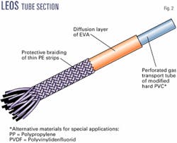
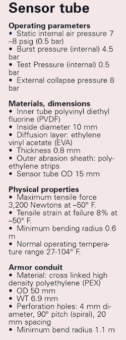
LEOS consists of a small (10-mm) diameter, perforated PVC tube with a thin (1-mm thick) outer ethylene vinyl acetate (EVA) sheath (Fig. 2). The tube perforations are 1-mm in diameter spaced uniformly 5-mm apart.
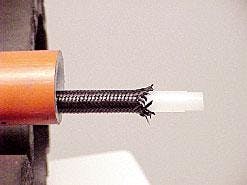
The acetate layer is impervious to water but allows hydrocarbon molecules (C1 through C6) to permeate through the membrane into the plastic tube. An outer layer of cross-woven PVC protects the inner tube from abrasion during normal handling (Fig. 3).
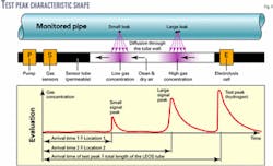
Air, cleaned and dried, is introduced into the tube at atmospheric pressure. In addition, a small amount of hydrogen is introduced at the beginning of each pumping cycle. This creates a small hydrogen "test peak" whose shape is used to calibrate the system.
The air filtering, drying, and test-peak generation are referred to as the "Test Peak Generator" (TPG) module. An activated carbon filter removes air particulates and a desiccant lowers the dew point to less than ambient values. A small hydrogen electrolytic cell generates a few cubic centimeters of hydrogen that are injected at the beginning of each air purging cycle.
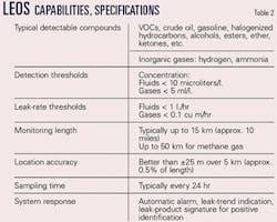
The arrival time and shape of the hydrogen peak (i.e., peak height to base ratio) is used to calibrate the fully automatic gas-detection module or measurement station (MS) at the far end of the system. Typically, the LEOS system can be up to 15 km long, depending on sampling cycle time requirements.
The MS module houses a vacuum pump and gas-sensing module. The module is an array of sensitive semiconductor gas sensors. These comprise an indirectly heated ceramic tube doped with stannous oxide. The change in resistivity of the semiconductor is logarithmic in the presence of the specific hydrocarbon.
The LEOS system detects a leak by collecting vapor due to the leak within perforated plastic tube. The liquid-impermeable acetate layer allows volatile hydrocarbon molecular constituents associated with the product to migrate through the layer into the tube. The gas concentration is proportional to the size of the leak outside the tube (Fig. 4).
The tube is sampled regularly by evacuating the air through the tube to the gas-detection module at the end of the tube at the MS module. The module sensors react to the presence of predetermined gases in the sampling air stream.
The leak can be located by timing the arrival of the indication and comparing this to the arrival of the calibration gas spike introduced into the tube at the beginning of the sampling cycle.
There is no typical air-cycle time for the LEOS system because the time to evacuate the air from the tube depends on the tube's diameter, the system's overall length, and a suitable air-residence time in the tube. The latter can be a function of the type of hydrocarbon to be detected and the soil type surrounding the tube.
The Northstar project team selected a sampling cycle time of 24 hr for the project based primarily on the 10-km distance and associated evacuation time of approximately 6 hr. This allows a sampling air-residence time of 18 hr in the tube.
The system's detection sensitivity depends on the type of hydrocarbon being detected, proximity to the leak, and to a lesser extent on the type of soil surrounding the sensor tube. Diffusion is equally effective in dry and saturated soils.
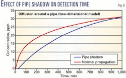
Fig. 5 shows the effect of tube position relative to the leak on sensitivity. If the tube is in the "pipe shadow," the migration (diffusion) time is attenuated by up to 1 hr depending on the pipe diameter.
The accompanying box shows characteristics of the sensor tube.
Design considerations
Every system component had to be evaluated for arctic application.
The LEOS PVC tube material was changed to a polyvinylidene fluoride (PVDF) material that was more suitable to bending in cold temperatures. The tubing was mechanically tested at –40° C. for bending and tensile strength. The outer abrasion mesh remained the same PVC material, as did the acetate impermeable sheath.
Although the arctic air is very dry in winter, there are times in the spring and early fall when fog envelops the coastline. The TPG module houses an activated-carbon filter to remove air-borne particulates and a bottled desiccant to dry the air below the lowest expected air temperature.
While the sampling air resides in the LEOS tube, a small amount of water vapor does migrate across the acetate membrane. As a precaution, the LEOS tube transition from sea to aboveground is heat traced and insulated to prevent any likelihood of condensation in the tube.
The Northstar pipeline route benefits from its relatively sheltered Beaufort Sea location within the seasonal landfast ice zone. The seafloor is nonetheless subjected to ice gouging, however. The extent of ice gouge depth depends upon water depth and soil type, among other parameters.5
A 100-year return period ice gouge depth of 0.7 m was established through statistical analysis of site-specific data collected over a 10-year period. A conservative design gouge depth of 1.1 m was used in determining pipe-soil interaction, allowable pipe strain, and displacements.
Strain and fracture toughness analyses indicate that the Northstar pipeline could safely develop a bending strain of up to 1.4% due to ice keel loading equating to a centerline radius of 9.8 m. This compares with the 1.1m minimum bending radius for the LEOS tube, which is strapped to the pipe.
Other external influences on the pipe and tube include the potential for differential settlement in the lagoon permafrost, strudel scour, and upheaval buckling.
Tube connection
It was necessary to re-evaluate the type of connector that would be used to join lengths of the LEOS tubing together.
Normally, a hose-clamp connector is used. But to minimize the number of metal components used in the connection, a completely new system was designed to resist the corrosive seawater environment.
A ferrule was machined from austenitic chromium-nickel (ASM A 302) stainless steel with excellent resistance to corrosion in sea water. The fitting fitted snugly into the ends of the LEOS tube ends. Plastic retaining clips were positioned and compressed over the tube ends clamping the ferrule, and a protective latex sheath held the clips in place before annular retaining clamps were secured over the grippers.
The completed assembly was enveloped in a heat shrink sleeve. Special tools and jigs were developed to ensure that the geometry and tolerances were strictly adhered to.
Mechanical axial tensile pull testing was performed at –20° C. to determine the breaking strength of the connection. The connector's breaking strength was slightly more than 80 kg force, which is almost twice that of the sensor tube.
PEX armor conduit
It was apparent from the outset that it would be necessary to protect the relatively fragile LEOS tube from mechanical damage during installation.
LEOS had previously been installed with a horizontal directionally drilled crossing (HDD); therefore, the exposure risk was not unprecedented. The tube was inserted into a slightly larger diameter polyethylene pipe strapped to the outside of the pipe HDD pull section.
Because the HDD project had been successful, the same plastic pipe ("PEX") was proposed for Northstar. PEX is a cross-linked polyethylene pipe normally used for pressurized potable-water service. Holes 4 mm in diameter spaced in a 20-mm square grid were drilled into the tube to allow rapid oil or gas product diffusion through the PEX wall and access to the LEOS tube.
Transportation logistics dictated that the LEOS tube would need to be delivered in 300-m coiled bundles. Because it would be highly beneficial to minimize handling the sensor tube on site, the project team decided to insert the LEOS tube inside the PEX armor pipe before loadout and transportation from the factory.
It was desirable to make the connector from non-metallic parts so that there would be no interference with the pipeline's passive cathodic-protection system. A connector was designed and manufactured completely from the same PEX armor pipe material.
The PEX material performed so well in full-scale laboratory tests that it became the material of choice. This connector proved superior in all respects to other commercially available plastic tube connectors that were prone to shatter upon impact at cold temperature.
Axial tensile loads were transferred through a labyrinth seal arrangement of machined grooves in the parent armor tube. A locking seal was inserted at both ends and slipped over the outside of the tube. After initial pull tests, the number of locking ring grooves was increased from two to three and the groove depth increased by 3 mm depth.
The aggregate cross-section bearing area of the interlocking grooves was twice that of the cross sectional area of the armor tube's wall thickness. The groove depth was limited to half the depth of the tube wall thickness.
It was vital to the success of the project to convince the installation contractors that the LEOS tube and PEX armor tube would withstand the rigors of construction. Mechanical impact tests were performed at the University of Alaska, Anchorage, where the cold laboratory facilities were used to freeze the PEX and LEOS tube prior to physical testing.
Tube samples were stored at -60° F. in a cold room. The specimens were removed and subjected to various bending and impact tests sufficiently rigorous to convince the contractor representatives that the material should withstand impact loads at the coldest ambient air temperature that might be expected during construction.
Pipeline bundle spacer
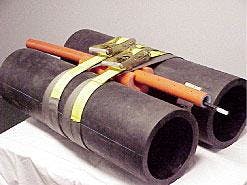
The pipeline was installed as a bundle (Fig. 6) with a polyurethane spacer separating the oil and gas lines. The spacers were installed every 12 m. The decision had to be made whether to install the LEOS tube at top dead center or at the bottom of the bundle.
Since leak-detection sensitivity would not be affected by the tube position, the decision was made to install the tube at the 12 o'clock position between the pipes out of consideration of protecting the tube from mechanical damage and ease of installation.
Between the bundle spacers, the tube was strapped to the oil line at 3-m intervals so that the backfill would not push down on the unsupported tube. The bundle spacer groove for the tube was molded to create a gentle curve transition to prevent severe localized tube bending.
Thirty-three 33 coiled LEOS and PEX bundles were air freighted to Fairbanks, Alaska, after which they were trucked to Houston Contracting Corp.'s warehouse at Prudhoe Bay. The 300-m capacity coils were stacked on pallets outdoors upon arrival on site because there was no requirement to warehouse them in a heated environment.
Although only 9.7 km of tube was required, spare tubing was ordered as a contingency. Houston Contacting designed and fabricated an insulated and heated sled capable of receiving a single tubing coil. Inside this habitat, the coil was given time (usually overnight) gradually to warm up before unreeling. An uncoiling rig was custom designed for the Northstar project.
The straightening device introduced a reverse bend into the PEX armor tube so that as it left the back end of the habitat, the tube was straightened to its originally manufactured geometry.
It is interesting to note that despite the reverse bending and straightening, the PEX tube has a tendency to "remember" its original configuration as it warms up, and there was no tendency for the tube to spiral or remain bent after straightening. The uncoiling habitat also served as an instrumentation console, spares, and tool shack.
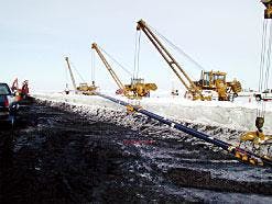
The PEX and LEOS tubes were strung out alongside the pipeline following welding, non-destructive testing, and field jointing activities. LEOS and PEX armor tube joints were made as soon as possible. The free tube ends were at all times protected from the environment with end caps.
Once the LEOS tube splice was made, the new section of tubing was pressurized to about 2 bar. Since the free flow of air from the tube is relatively gentle, it was unnecessary to wait for the tube to depressurize before making a splice. Alaskan journeymen under vendor supervision performed all tube splicing.
Once the first pipeline string was welded, the bundle spacers were attached to the line, and the LEOS tube was attached to the pipeline bundle before the second pipe was matched up. This sequence continued to the end of the pipeline section.
The pipeline was constructed in two 3-mile sections to facilitate diurnal pipe expansion and contraction. The LEOS tube was installed as a continuous string and proved easy to handle and finally pull out slack once the final tie-in welds were made.
There were minimal logistical difficulties with installing the LEOS tube as part of the bundle and the LEOS tube caused no logistical difficulties to the pipeline welding or field jointing activities. When the completed pipeline bundle was ready for lowering, the LEOS tube was secured between the pipes so that it would not snag or be crushed between the pipe lowering-in rollers (Fig. 7).
Shore crossing; island
The subsea-to-aboveground transition is critical for the pipeline, as can be seen from the vertical transition riser for the pipeline. The transition at the shore crossing introduces the added complication of long-term pipeline movement in the vertical and horizontal planes due to pipe thermal growth and long-term thaw settlement.
The pipelines make this transition in a vertical riser shaft that acts as a sleeve around the pipes, leaving them free to move when they warm up. Here, the LEOS tube is firmly strapped between the pipes to protect it from differential loads due to the soil backfill surcharge.
A layer of select backfill gravel was placed under the pipe so that when thawing occurs the settlement will be within acceptable limits (up to 1 ft under the vertical riser). Elsewhere, through the lagoon area out to Stump Island, permafrost is encountered, and differential settlement of up to 2 ft is accounted for by the design. Most of the thawing will take place within the first 2-3 years of operation.
The pipeline will be monitored with internal-inspection tools to measure pipe geometry to determine the extent of movement. Since the Young's Modulus for PEX is many times smaller than for steel, any anticipated pipe movement should pose no risk for the LEOS tube.
Likewise, beyond the lagoon in the portion of the route potentially exposed to the deepest ice keel gouging (6-ft trench depth of cover), the tube will remain between the pipes. If any movement should occur, it would be limited to the extent of pipe movement.
The tube is strapped to the pipeline and must negotiate two right-angled bends within the vertical riser shaft. These are 5-D (1.3 m radius) bends subjecting the tubing to its severest bending.
The LEOS tube transitions out of the vertical riser at the shore through a sleeve insert into the PEX armor tube. Once above ground, the LEOS tube is no longer perforated and as soon as it exits the riser shaft, the LEOS PVDF tubing is changed to 0.5-in. diameter stainless steel tubing via a custom designed coupling.
A protective shroud was designed to prevent inquisitive bears accessing the coupling and the plastic LEOS tube. After exiting the riser shaft, the stainless steel tubing is routed along the gas line and via a 2-in. fuel-gas-line takeoff over to the remote terminal unit (RTU) building.
An insulated metal box is provided under the building to store a 300-m length of LEOS buffer tubing before the stainless steel tube enters the RTU building where it is hooked up to the TPG cabinet.
The buffer tubing, which is not perforated, serves as a virtual length of uncontaminated air (i.e., no traces of background methane or other exhaust contaminants). This buffer length cues the measurement system to the arrival of the hydrogen test peak.
Fresh air is drawn into the TPG cabinet via an inlet diffuser mounted on the outside wall of the RTU building. The air-inlet diffuser is to prevent snow from blocking the air intake line. The air is passed through an activated-carbon filter and desiccant jar before traveling into the LEOS sensor tube.
The transition into the Northstar production island differs from the shore crossing.
Instead of the vertical riser used at the shore crossing, the pipeline transitions into the island with a sweeping vertical curve equal to the slack radius of the steel pipeline. The pipeline enters the island under a sheet piled steel wall.
The transition from subsea to above ground requires that the tube be heat traced to prevent water vapor condensation inside the tube. Although the rate of diffusion of water across the acetate membrane is very slight, over the 10-km length of the tube this could accumulate if there were a vacuum-pump breakdown or power outage for a longer period (several weeks).
As a precaution, heat tracing was applied at the waterline all the way to the measurement module. The LEOS tube was terminated approximately 4 ft below the level of the dock at elevation +10 ft and transitioned with 0.5-in. TPE (reinsulated stainless steel tubing with self regulating electric tracing).
Pre-operation; checks
The sealift logistics for piping-module delivery to the production island made it necessary to install the LEOS system in two phases, 12 months apart.
The LEOS tube was installed during the pipeline installation prior to the first-year sealift of drilling production modules from Anchorage to the island in summer 2000. The TPG cabinet in the RTU building at the shore crossing was also installed during Phase 1, although there was no power during the next 12 months.
Since the tube should not be left underwater for more than a few weeks without evacuating the air, it was also necessary to hook-up a temporary air-pump module at the production island so that air inside the tube could be periodically evacuated. This was required so that moisture resulting from water vapor would not become trapped inside the tube before the system was made operational.
Construction Phase 2 in summer 2001 (prior to production start) included powering up the TPG cabinet at the shore crossing, hooking-up the LEOS tube with stainless steel tubing on the island, and starting up the measuring station inside the warehouse on Seal Island. Due to the many construction activities on the island, it was necessary to move the air-pump module several times during the 2 years following Phase 1 installation.
The LEOS tube was pressurized and depressurized daily as precaution until a temporary air pump was hooked up.
After the air pump was installed, a system functional check was made at the end of June 2000. At that time, background methane levels along the pipeline route were also measured. During the summer months, access to the shore crossing is limited to a water route. Therefore, servicing of components is not readily achievable.
The battery pack that provides energy for the hydrolysis to generate the hydrogen test peak has a 1-year life. Other components within the TPG cabinet include the activated-carbon filter and desiccant which are factory installed and require only annual servicing.
Periodic checks were necessary to ensure that the pump is working normally (every 7 days).
Before pipeline start-up, technicians visited the site to check on the system using a portable LEOS measuring device. The system was fully functional and the results of the test trace output were interesting.
Many hydrogen spikes can be seen corresponding closely to the sacrificial anodes attached to the pipe for cathodic protection. The anodes function electrolytically, and hydrogen is evolved through the electrolytic process due to the seawater reacting with the aluminum bracelet. This is not a surprising result and the possibility was envisioned during conceptual design.
The extent of this was not quantified, however. The presence of the hydrogen spikes is a nuisance because it masks the single calibration spike that is an important feature of the LEOS system. A selective catalytic converter has been installed that oxidizes the hydrogen to water vapor so that anode-generated hydrogen spikes no longer register at the measurement station.
More recently, a modem link enables Framatome technicians remotely to monitor the daily outputs and advise the operating staff regarding the significance of a changing indication.
After a year of operation, the LEOS system has been field calibrated to account for increasing background methane due to soil warming. The evolution of hydrogen from the sacrificial anodes has been remedied by insertion of a catalytic converter module ahead of the measurement station, thereby preventing false alarms.
The ability to detect the hydrogen from all the anodes demonstrates that the cathodic protection system is functioning. It also enables individual anodes to be discerned and provides an opportunity to improve the accuracy of a potential leak location.
Acknowledgments
The authors thank BP Exploration (Alaska) Inc., INTEC Engineering Inc., and Framatome ANP for permission to publish this article.
References
- Braden, A., Manikin, V., Rice, D., Swank, G, Hinnah, D., Monkelien, K. and Walker, J., "First Arctic Subsea Pipeline Moving to Reality," 1998 Offshore Technology Conference, Houston; Paper No. 8717.
- Hovey, D. J., and Farmer, E.J., DOT Stats indicates need to refocus pipeline accident prevention, OGJ, Mar. 15, 1999. p. 52.
- US ACE, Final Environmental Impact Statement; 1999 Beaufort Sea Oil and Gas Development/Northstar Project, US Army Corps of Engineers, Alaska District, Anchorage.
- Issel, Wolfgang R. J., and Swiger, P., "LASP – A Leakage Alarm System for Pipelines," Pipeline Industry, June 1985.
- Lanan, G. A., Nogueira, A. C., McShane, B. M., and Ennis, J. O., ''Northstar Development Project Pipelines Description and Environmental Loadings'', International Pipeline Conference, May 2000, Calgary.
Based on a presentation to the International Pipeline Conference (ASME), Sept. 29—Oct. 3, 2002, Calgary.
The authors
Peter Bryce is president of Brytech Consulting Inc., Delta, BC, having consulted for the oil and gas industries since 1996. He began his career in the North Sea on the Piper and Claymore developments before emigrating to Canada. He holds a bachelor's (1974) in civil engineering from Loughborough University of Technology (UK) and is a registered professional engineer in the province of British Columbia.
Peter Jax is engineering project manager in the department of measurement and inspection techniques of FANP, Erlangen, Germany, which he joined in 1982. He has also served as a senior scientist for Battelle in Frankfurt 1971-82. Jax holds a PhD in physics from the University of Cologne in Göttingen.
Jie Fang is deputy manager of riser engineering for INTEC Engineering Inc., Houston. Previously he was head of the analysis section of the engineering department of European Marine Contractors Ltd., Surrey, UK. Fang holds a BSc (1985) from Shanghai JiaoTong University, China, and a PhD (1992) from the University of London, both in naval architecture and ocean engineering.
