Technique yields exact solution for planning bit-walk paths
Bit walk is the natural tendency of the drill bit to drift in a lateral direction during drilling and occurs in every operation. Operators planning and designing wellbore trajectories, therefore, must consider planning 3D paths, especially in areas where the amount of bit walk is considerable.
Effective 3D-well paths reduce azimuth correction frequencies and the workload of trajectory control, reduce wellbore tortuosity, reduce the number of drillstring trips, improve penetration rates, and ultimately reduce drilling costs.
Drilling experience has shown that operators can use bit walk effectively to control well trajectories, if drilling experience allows accurate estimation of the bit-walk rate.
The authors have developed a mathematical model, which they call the natural-curve model, along with several methods for planning various bit-walk paths.
Compared with conventional well-path calculation methods, the model has several advantages:
- The model directly accounts for bit-walk effects in trajectory calculations. Results have demonstrated that it is possible to avoid path corrections by appropriate prediction of the bit-walk rate over each well-path section for directional and horizontal drilling.
- Operators can use the model for planning various 3D paths, including slanted wells, directional wells, and horizontal wells. It effectively calculates well paths with any combination of arc and straight sections in the vertical expansion plot.
- All of the model parameters of the wellbore trajectory become explicit functions of measured depth.
- Compared with the radius of curvature and minimum curvature methods, which are used routinely worldwide to simulate and calculate drilled wellbore trajectories, the natural-curve model yields more accurate and stable results.
- The model employs an exact mathematical solution.
Several examples of well-path planning, which the authors present, test and verify the accuracy and applicability of the natural-curve model. The model and formulas, programmed into computer software, have proven satisfactory for hundreds of directional and horizontal wells in China.
Bit walk
Bit walk occurs in drilling operations as well trajectories are drilled, generally occurring as right-hand drift but also occasionally as left-handed drift.
Operators customarily kick off a directional well with a lead angle to compensate for the influence of bit walk on the well trajectory. But designers still simplify well-path design at the planning stage, containing it within a vertical plane.
Current well-path designs only append a lead angle to the 2D-well path, which is hardly possible to satisfy the requirements of actual drilling operations.
The industry has presented several methods for evaluating the rate of bit walk and the lead angle required, but few articles relate to actually planning a bit-walk path.1,2
Based on the assumption that bit-walk rates of inclination change and azimuth change remain individually constant over each section, the authors present the advanced natural-curve model to describe the bit-walk path.
The authors also developed appropriate methods for planning 3D-well paths for slanted wells and directional and horizontal wells with any combination of arc and straight sections in the vertical expansion plane.
In directional drilling, the industry describes bit-walk behavior as the rate of azimuth change. Accordingly, the model and methods discussed provide mathematically consistent techniques, not only for planning bit-walk paths, but also for other 3D path calculations.
Because of this, the model and methods presented apply to path corrections and survey calculations.
Mathematical model
Generally, the industry plans a well path in a 2D plane, creating a profile of arcs and straight sections. An essential character for this kind of profile, the rate of inclination change must remain constant in each section.
The tendency and degree of bit walk indicates the bit-walk rate, which relates not only to formation anisotropy but also to bit anisotropy and bit type, bottomhole assembly configuration, and drilling operational parameters.
Wellbore designers can consider the bit-walk rate to remain constant in each section if drilling parameters do not change much within each section length and this remains true for every section over the entire wellbore trajectory.
Equations 1 and 2 define inclination and azimuth as linear functions of measured depth, assuming the inclination and azimuth change rates remain individually constant in each section (accompanying box).3
One can use vertical expansion plots and horizontal plots to project wellbore trajectories. A zero vertical build rate, ka = 0, will depict a linear section and non-zero vertical build rate, ka not equal to 0, will depict an arc section.
If the well path is a holding section with no inclination build, ka = 0, a zero azimuth build rate, k azimuth angle = 0, will depict a linear section and non-zero azimuth build rate, k azimuth angle not equal to 0, will depict an arc section, on horizontal plots.
Substituting Equations 1 and 2 into the differential model of wellbore trajectory yields Equations 3-6 through integral calculation, which well designers can use to calculate the course coordinates.
In field terms, the industry usually reports angles in degrees. But computer programs normally use radians for angle units.
Calculations require angle unit conversion and consistent build rate units. Equation 7 simplifies the functions, FS(u, k) and FC(u, k), if inclination and azimuth are given in radians and the rates of inclination change and azimuth change are provided in radians per meter.
The mathematical theory of curves defines the length parameter of a curve as the natural parameter. All parameters of wellbore trajectory in this model are functions of measured depth.
Thus the authors have named this model for describing wellbore trajectory as the natural-curve model.
Inclined well
The inclination angle of a slanted well remains constant from wellhead to target. For this long holding section, however, drilling engineers must pay attention to the problem of bit walk to ensure the well arrives at the planned target.
Although the inclination angle may remain constant, the well path does not follow the straight line connecting the wellhead with the target. Simple inclined wells follow a 3D path, as a result of the inevitable bit walk.
Since the inclined or slanted well has no build or drop rate, the condition ka = 0 applies and one can analyze and simplify Equations 3-6 to yield Equations 8 and 9.
The deflecting performance of rock layers affects the rate of bit walk more significantly than the other contributing factors of bit type, bottom-hole assembly configuration, and drilling operation parameters.
Operators must drill oil and gas wells through thousands of meters of formation rock to reach target reservoirs. Wellbores traversing long intervals often cross multiple rock layers that have different properties based on sedimentology and lithology.
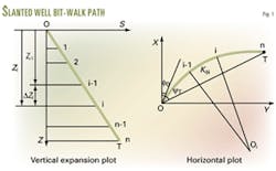
Well designers should, therefore, divide a slanted well into a number of vertical sections, to ensure the bit-walk rate remains relatively constant within each interval traversed (Fig. 1). Accordingly, a combination of straight lines and arc sections define the horizontal plot, with the intervals labeled from 1 to n.
This concept combined with Equations 8 and 9 yields Equations 10-13, which provide a way for planning the bit-walk path of a slanted well by evaluating measured depth, azimuth angle, and horizontal departure.
Solving the wellbore trajectory requires iterative calculations to determine the well inclination, a, and initial azimuth, azimuth angle0.
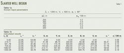
For an example of planning the bit-walk path of a slanted well, Table 1 lists the bit-walk rate for each interval of a well divided into five vertical sections, according to the formation's drilling characteristics.
Table 2 shows a summary of the calculated well plan, indicating a total azimuth change of 12.10°, a lead angle of 5.32°, and a calculated bit-walk inclination path of 22.65° that is slightly different from straight line path of 22.62°.
Directional well
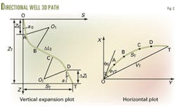
Fig. 2 shows the typical profile of the bit-walk path for an "S" shaped directional well. Although several methods are available for planning 3D-well trajectories, they do not plan bit-walk paths suitably, primarily for two reasons.
First, unlike a spatial arc, the bit-walk section does not lie on a plane in space, so is impossible to convert into a 2D shape.
Secondly, the shape of a bit-walk section in the horizontal plot, generally does not match that of a simple curve, such as an arc or straight line. Such a complicated combination of curves makes it difficult to design the horizontal plot.
In fact, the parameters of a bit-walk profile, being interrelated and interdependent, make it too difficult to solve the problem with the aid of 2D-well path planning methods.
But without doubt, operators must design the well path to reach the predetermined target.
Therefore, Equations 14-16 define the sum of the coordinate increments over every section, which must equal the measured depth through the well path between the wellhead and target.4
In theory, Equations 14-16 equal Equations 17-19, but the later set of equations has demonstrated better convergence and efficiency in the calculation process during a great deal of well planning experience.
Planning 2D directional "S" shaped wells requires the length and inclination of the third section, or the hold section (BC), as a key parameter (Fig. 2).
Also, when planning 3D directional wells, the well designer must determine the initial azimuth or the lead angle as a supplementary parameter. Equations 17-19 enable a solution to the problem.
The second example covers design of an "S" type directional well involving bit walk, given the following input data:
- Initial inclination,
- a0 = 15°.
- Total vertical depth at kick-off-point, ZK = 400 m.
- Target point, ZT = 1,500 m.
- Horizontal displacement, VT = 600 m.
- Azimuth angle of horizontal displacement, Azimuth angle of horizontal displacement lineT = 120°.
- Final section inclination, af = 10°.
- Final section vertical depth change, ΔZf = 100 m.
- Vertical build rate of buildup section, ka2 = 2°/30 m.
- Vertical drop rate of drop-off section, ka4= -1.5°/30 m.
- Sectional bit-walk rates, 0.3°/30 m, 0.8°/30 m, 0.6°/30 m, 0.4°/30 m, and 0.5°/30 m, successively.
According to the natural-curve model with above method, the planned results of the bit-walk path show that a3 = 31.78°, ΔL3 = 429.59 m, and azimuth angle0 =106.32°, with a lead azimuth angle of 13.68°.
This compares with key parameters determined from the 2D-well path planning method, which are a3 = 31.21°, ΔL3 = 446.87 m, and azimuth angle0 = 120°, clearly with considerable difference between the results of the two methods.
Table 2 shows the calculated results of the bit-walk path method, with the wellhead coordinates given as XW = 100 m, YW = 200 m and ZW = -50 m, which test and verify universal applicability of the method.
Horizontal well
When planning a horizontal well, the engineers normally design the horizontal section first and then plan the path from the wellhead to the landing point. By convention, inclination and length define a 2D horizontal section.
If the operator requires a 3D horizontal section, the planners normally design its starting point, end point, and path shape to satisfy the geology and exploration and production requirements.
Geologists and oilfield development and drilling experts should strive to fine tune horizontal well designs. Engineers can drill horizontal laterals, in theory, that have combinations of curves with multiple inclination and azimuth changes.
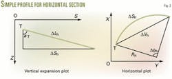
Fortunately, most existing horizontal sections have required relatively simple designs. Fig. 3 shows the simplest profile of a 3D horizontal section, maintaining the inclination at a constant rate of azimuth change.
Equations 20 and 21 calculate the horizontal section's length, ΔLh, and azimuth change, Δfh, given the inclination, aT, and rate of azimuth change, k azimuth angleh, parameters. If azimuth change is zero, k azimuth angleh = 0, Equations 20 and 21 express a 2D horizontal section.
After designing the horizontal section, the operator has effectively set the position and path direction of the landing point and the path shape leading into the horizontal section.
Planning the wellbore trajectory above the horizontal section, with the given direction at the target, adds restricted conditions mathematically, and increases the difficulty and complexity of the problem.
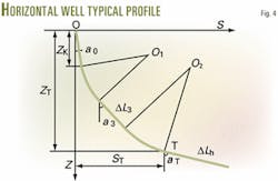
Fig. 4 shows a typical horizontal well profile with two build sections. From the above procedure, operators must calculate three key parameters, for planning a 3D directional well.
When planning a 3D horizontal well, however, operators must determine four key parameters because the azimuth at the landing point was fixed from the planned results of the horizontal section.
Theoretically, the well designer can choose and solve for any four key parameters from all well path parameters. For this example, the authors have chosen length, inclination, rate of azimuth change of the third section, and the initial azimuth of well path.
Equations 22-25 determine the values of the four key parameters. If the designer does not confine target azimuth, fT, to a predetermined value, he should give a fixed value to the rate of azimuth change over the third section, k azimuth angle3. Also, Equation 23 will not create a restricting condition.
The third example plans a 3D horizontal well, given the following input data:
- Horizontal section inclination, aT = 88°.
- Horizontal section displacement, ΔVh = 600 m.
- Initial inclination, a0 = 15°.
- Total vertical depth at kick-off-point, ZK = 1,000 m.
- Landing point, ZT = 1,200 m.
- Horizontal displacement, VT = 500 m.
- Azimuth angle of horizontal displacement, cT = 260°.
- Horizontal section azimuth, fT = 266°.
- Vertical build rate of first build section, ka2 = 8°/30 m.
- Vertical build rate of second build section, ka4= 10°/30 m.
- Sectional bit-walk azimuth change rates, 0.3°/30 m, 0.6°/30 m, 0.2°/30 m, and -0.5°/30 m, successively except the third section.
Equations 20 and 21 calculate the horizontal section's azimuth and length change, as Δfh = -10.02° and ΔLh = 601.13 m.
Table 3 shows the calculated results for the horizontal well. According to the procedure reviewed above, the design of the wellbore trajectory above the horizontal section resulted in
azimuth angle0 = 250.89°, δL3 = 78.88 m, a3 = 49.65°, and k azimuth angle3 = 0.53°/30 m, which results in a lead angle of 9.11°.
Survey calculation
Operators must monitor wellbore trajectories during the drilling process. But inclinometers can only give elementary parameters from separate survey points and cannot give the real well trajectory profile.
As a result, every survey method bases the calculations it performs on assumptions.
Most of these assumptions rely on typical curves, such as cylinder helix and circular arc.5
Real well trajectories exist in 3D space. The inclination and azimuth readings at the survey stations, taken at multiple points, provide the degrees of change in the well trajectory and correspondingly the inclination and azimuth change rates.
Therefore, inclination and azimuth change rates provide effective means for calculating the wellbore trajectory directly.6
Equations 26 and 27 calculate inclination and azimuth change rates from the surveying instrument readings obtained at various depths.
One can very easily calculate course coordinates within a survey interval, from the assumption that the rates of inclination and azimuth change remain individually constant, as assumed during derivation of Equations 3-6.
Table 4 presents the results of an example designed to verify the natural-curve model calculated results and compare the results with the radius-of-curvature and minimum-curvature methods, which are routinely used in the oil field.
The example assumed the length of survey interval to be DL = 30 m, the upper survey station to have inclination and azimuth of a1 = 30° and f1 = 60°, and the lower to have a2 = 36° and f2 =72°.
Compared with the radius-of-curvature method and minimum-curvature method, the most commonly used methods in the oil field, the natural-curve method generated accurate and stable results.
Click here to view Equations Chart
References
- McMillian, W. H., "Planning the Directional Well-a Calculation Method," SPE paper No. 8337, 1979.
- Maidla, E. E. and Sampaio Jr., J. H. B., "Field Verification of Lead Angle and Azimuth Rate of Change Predictions in Directional Wells Using a New Mathematical Model," SPE paper No. 19337, 1989.
- Planeix, M.Y., and Fox, R.C., "Use of an Exact Mathematical Formulation to Plan Three Dimensional Directional Wells, " SPE paper No. 8338, 1979.
- Xiushan, L., et al., "Design of a 3-D Drift Well-path," Acta Petrolei Sinica, Beijing, Vol. 16, No.4, 1995, pp. 118-24.
- Callas, N.P., et al., "Directional Survey Calculation Methods Compared and Programmed, " OGJ, Jan. 22, 1979, p. 53.
- Xiushan, L., et al., "Natural Parameter Method Accurately Calculates Wellbore Trajectory, " OGJ, Jan. 27, 1997, p. 90.
The authors
Xiushan Liu is a professor at Sinopec Corp.'s Exploration & Production Research Institute, a visiting professor at CNPC's Key Laboratory of Drilling Engineering, and a part-time professor at Daqing Petroleum Institute in China. He has a BS and an MS from Daqing Petroleum Institute and a PhD from Research Institute of Petroleum Exploration & Development of CNPC, all in petroleum engineering.
Zaihong Shi is reading for her PhD at the Institute of Mechanics of the Chinese Academy of Sciences in China. She received her BS and MS in petroleum engineering from Daqing Petroleum Institute. Her professional experience includes work as an associate professor at Daqing Petroleum Institute and Tsinghua University.
