Tubular imperfections pose design problems in short, ultrashort radius wells
With the emergence of short and ultrashort-radius horizontal wells, tubular failures have become increasingly common. Such wells encounter severe bending stresses that well designers may not have considered when calculating tubular collapse strength.
This article demonstrates that a finite-element model can calculate the stresses acting on out-of-round tubulars and assess oval casing collapse-strength resistance.
In severe doglegs, the oil and gas industry has observed that oil field tubulars collapse at pressures considerably less than API's recommended procedures would predict. The API procedures do not account for casing deformation.
In short and ultrashort-radius wells, casings that are set in severe doglegs under tensile load cannot preserve their circular geometry and the cross-sections become more of an ellipse than a circle.
The amount of deformation or extent that the casing is out-of-round depends on casing diameter, WT, tensile force, and dogleg severity. External pressure will further flatten the tube that is already out-of-round.
External pressures that can cause the yielding in the extreme fibers of initially out-of-round casings are significantly less than API's collapse pressures would estimate based on circular geometry.
Tubes in curved boreholes
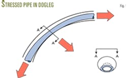
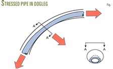
The industry has assumed that oil field tubulars preserve their physical dimensions once they have been run into a borehole. The assumption is not always true and often leads to serious problems when running tools within the tubes (Fig. 1).1
Engineers know that the tube's weight and bending within a curved borehole cause the extensive axial stresses.2
The use of tubes in curved boreholes requires three-dimensional analysis of deformations and stresses, rather than a unidimensional analysis. Although engineers have done some work to quantify the deformation of tubes in pure bending, most of it was for submarine pipelines.3 4
Until the last decade, the study of tubular deformation did not use the loads and bending common to oil well borehole conditions.
Various disciplines have long used the finite-element method (FEM) to analyze deformations and stresses in solid structures. The authors demonstrate FEM use in oil well boreholes.
Finite-element method
Workers first studied the important deformations of a tube, internal diameter reduction (ovality) and elongation (stretch), by means of FEM, publishing the results in 1992.1
The finite-element model selected in this study was an eight node, isoparametric, thin-shell element with inplane and plate-flexure deformation capabilities.
The two nodal forces were the weight of the tube hanging below the node of interest, and the contact force between the borehole and the tube at the node of interest. The size of the gap between the tube and the wall of the hole set the nodal boundary conditions.
The authors modeled a 30-ft API casing with standard API collars, using a rigid ring to model the tube coupling, and assigning a perfect circular configuration to all borehole builds or doglegs.
The model applied only shear and axial loads at the tube's collar end. Reaction shear loads naturally developed along the borehole wall where the tube contacted the wall.
Over the length of the tube, the model calculated the initial gap sizes between the tube and borehole, mandating that the tube would be straight and the builds or doglegs would be circular.
The model assigned the element nodes on the side of the tube, which contact the borehole, with displacements equal to the gap sizes, except where the collar dictates that a gap always exists.
Out-of-round tubulars
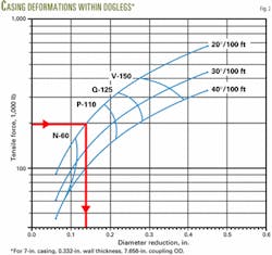
Fig. 2 is the graphical representation of a finite-element analysis of the tubular deformation for 7-in. casing with 0.332-in. WT and 7.656-in. OD coupling.
With tensile forces applied to the casing ranging from 40,000 to 1 million lb, the analysis considered hole curvatures of 10°, 20°, and 30°/100-ft dogleg severities (Fig. 2).
Inside a 20°/100-ft dogleg, the graph shows that a 200,000-lb tensile force can reduce the diameter of this casing by about 0.13 in. The casing no longer would be circular but rather would have an elliptical cross-section.
Tube collapse strength
Failure of out-of-round tubes under uniform external pressure depends largely on various imperfections.5 6 The most common tube imperfection is the initial degree of ovality or extent of being out-of-round.
To formulate the collapse-pressure resistance of deformed casing, workers can use the concept of compressed rings and curved bars buckling in the theory of elastic stability.
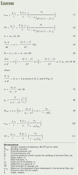
Equation 1 shows that the maximum compressive stress on the wall of deformed casing depends not only on the initial amount of diameter reduction or amount that it is out-of-round, w0, but also on the external pressure, p (see accompanying box).
The maximum external pressure that deformed casing can resist occurs when the maximum compressive stress in the extreme fiber, σmax, becomes equal to the casing's yield strength, YP (Equation 2).
The example illustrated by Fig. 2 shows that the diameter of 7-in. casing reduces by 0.13 in. after it has been run into a hole with 20°/100-ft dogleg severity and under 200,000-lb hanging weight.
Equation 2 can determine the collapse-pressure resistance of this deformed casing as follows:
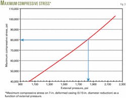
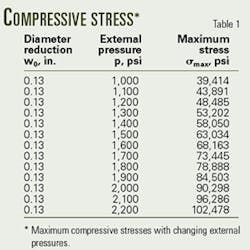
- Substituting different external pressure values into Equation 1 generates values for casing wall maximum-compressive stress, σmax, given the initial value of the casing being out-of-round (Table 1, Fig. 3).
- By selecting the yield strength of the casing in question, Fig. 3 directly indicates or predicts the collapse-pressure resistance of the 7-in. deformed casing. For example, a 7-in. deformed N-80 casing will collapse at 1,820 psi (Fig. 3).
Oil field tubular design
A fundamental approach in designing oil field tubulars for a given borehole condition is to select tubulars that will be stronger than the maximum expected stress. The approach calls for anticipating the stresses and predicting tube strength.
Since tubulars in a severe dogleg cannot retain the original shape, strength is less than a circular tube.
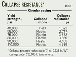
Table 3 shows the casing collapse pressure resistance of 7 in., 0.332-in. WT, for grades H-40, K-55, C-75, N-80, and P-110, calculated by applying API's recommended procedures.
These pressures are normally what the casings are expected to support in a straight-hole condition.
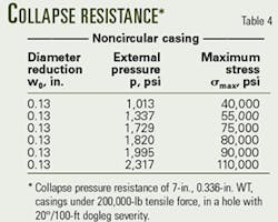
The same casing strings would ovalize, with about 0.13-in. diameter reduction, when run into a wellbore with 20°/100-ft dogleg severity and 200,000-lb tension force (Fig. 3).
Calculated with the methods discussed, Table 4 lists the collapse-pressure resistances of deformed casings of the same grade.
Comparing the collapse-pressure values of Tables 3 and 4, for circular and noncircular casing, reveals pressure differences up to 50% occurring.
The actual casing design factors in wells with severe dogleg conditions could be substantially less than engineers would have calculated assuming circular geometry. The situation worsens if the external pressure increases—increased pressure flattens the already deformed tube even more.
By solving the differential equation of the deflection of a curved ring, one can determine the additional flattening or deformation of the tube as external pressure increases (Equations 3 and 4).
Once the additional flattening is quantified, Equation 2 will estimate the remaining collapse strength of the flattened casings.
Since casing collapse strength declines as a function of increased deformation, further reduction occurs when the casing flattens under the action of external pressure.
External uniform pressure
The failure of tubes under uniform external pressure depends on various kinds of imperfection, but the most common is the initial extent that the tubes are out-of-round.
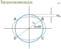
A tube's ellipticity or ovality is the radial deflection of its mean radius. The magnitude of the mean radius maximum deflection defines the initial ellipticity, w0 (Fig. 4).
The radial deflections are not uniform along the mean radius line, but symmetric according to major and minor axes of the ellipse. Equation 3 calculates radial deflections in terms of w0 and θ.
In Equation 3, θ is the angle measured in the counterclockwise direction from the ellipse's major axis, w0 is the maximum initial deflection at θ = 0, and w is the radial deflection of the mean radius at θ ≠ 0.
The action of external uniform pressure, p, will cause additional flattening of the tube and a corresponding radial displacement, w.
Solving the differential equation of a curved-ring deflection will determine the corresponding radial displacement, w. Workers can determine w, with use of the differential equation of the deflection of a curved ring (Equation 4).
The bending moment is zero at points A, B, C, and D (Fig. 4). A uniform external pressure will produce a positive bending moment in portions AB and CD and a negative bending moment in portions AD and BC.
The compressive force along this curve remains constant. Multiplying the compressive force by the total radial displacement, wi+w, at this cross-section yields the bending moment at any cross-section (Equation 5).
Substituting Equation 5 into 4 yields Equation 6. Satisfying the conditions of continuity at the points A, B, C, and D, the solution of this equation becomes Equation 7.
In the case of a long circular tube, uniformly compressed by external pressure, Equation 8 gives the uniform pressure critical value, pcr.
The bending moments at points A, B, C, and D are zero, which means that deflection, w, and Equations 4 and 6 become zero at these points as well. The maximum bending moments occur at θ = 0 and at θ = π/2, as given by Equation 9.
For small values of the ratio p/pcr, the change in the ellipticity of the tube due to pressure, p, can be neglected. The maximum bending moment can be obtained by multiplying the compressive force, pr0, by the initial deflection, w0.
When the ratio p/pcr is not so small, one should consider the change in the initial ellipticity of the tube and use Equation 9 in calculating Mmax.
Equation 10 calculates the maximum compressive stress by adding the stress produced by the compressive force, pr0, to the maximum compressive stress due to bending moment, Mmax.
Assuming that Equation 10 provides enough accuracy up to the yield-point stress of the material, then Equation 11 will calculate the uniform pressure, pc, when yielding in the extreme fibers begins.
References
- Akgun, F., Mitchell, B.J., and Huttelmaier, H.P., "Ovality and Stresses of API Tubulars in Horizontal Wells with FEM," Paper No. SPE 24613, presented at the SPE Annual Technical Conference, Washington DC, Oct. 4-7, 1992.
- Lubinski, A., "Maximum Permissible Dog-Leg in Rotary Boreholes," Journal of Petroleum Technology, February 1961, pp. 175-194.
- Kyriakides, S., "On the Stability of inelastic circular pipes under combined bending and external pressure," Systems Engineering Society of Australia proceedings, Spring 1981, pp. 372-378.
- Nomoto, T., Enosawa, M., and Fujita, Y., "Analytical Study of the Collapse Strength of Submarine Pipelines," Seventh Ocean Engineering Symposium, Society of Naval Architects of Japan, 1984, pp. 169-178.
- Timoshenko, S., Strength of Materials, Part II, third edition, Van Nostrand Reinhold Co., New York, 1958.
- Formulas and Calculations for Casing, Tubing, Drill Pipe, and Line Pipe Properties, American Petroleum Institute, API Bulletin 5C3, revision 94, 1999.
- Blake, A., "Deflection of a Thick Ring in Diametral Compression by Test and by Strength of Materials Theory," Journal of Applied Mechanics, June 1959, pp. 294-295.
- Weydert, J.C., "Stresses in Oval Tubes under Internal Pressure," Proceedings of the Society for Experimental Stress Analysis, Vol. 12, No. 1.
- Wu, J. and Juwkam-Hold, H.C., "Discussion of Tubing and Casing Buckling in Horizontal Wells," Journal of Petroleum Technology, August 1990, pp. 1062-1106.
The authors
Ferda Akgun is a professor of petroleum engineering at UAE University, United Arab Emirates. He has worked on research projects and consulted with major oil companies in North America, the Middle East, and Australia. He has supervised graduate students at the University of New South Wales, Sydney, Curtin University, Perth, and UAE University. He received a PhD (1989) in petroleum engineering from Colorado School of Mines, Golden. He has been a member of SPE for 18 years.
Alfred William Eustes III is a professor of petroleum engineering at the Colorado School of Mines, Golden. He has 24 years of drilling and production experience, 9 years with the former ARCO Oil and Gas Co. He has a BS in mechanical engineering from Louisiana Tech University, Ruston, MS in mechanical engineering from the University of Colorado, Boulder, and PhD in petroleum engineering from the Colorado School of Mines. He is a registered professional engineer with the state of Colorado and a member of ASME, SPE, American Association of Drilling Engineers, and the IADC.
