DRA increases Indonesia pipeline capacity to allow accelerated field production
Use of a drag-reducing agent (DRA) allowed an Indonesian pipeline system to overcome capacity constraints quickly, bring on stream additional crude production, and shut down some pumping capacity at substantial savings.
Use of DRA also helped operator PT Exspan Nusantara (PTEN) to overcome line capacity limits on the Samboja-Balikpapan pipeline in East Kalimantan, permitting delivery of more crude production from new discoveries at the NKL field and preventing stock buildup at the main oil station at Sangasanga.
Sumatra field
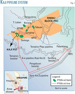
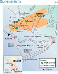
The Kaji-Semoga (KS) field, in south Sumatra, Indonesia, began producing in March 1997 from proved reserves of 77 million bbl of oil and peak production forecast at 40,000 bo/d in 1999-2000. To transport KS production to the 125,000-b/d Plaju refinery, field operator PTEN built two pipelines of 4-in. OD each tied to the Tempino-Plaju pipeline and one 8-in. OD pipeline tied to PTEN-owned Jene-KM.3 pipeline with three booster pump stations (Fig. 1).
As developmental drilling continued, reservoir calculations increased proved reserves to 135 million bbl and peak-production forecast to 68,000 bo/d in 2001. Problems due to limited pipeline capacity became quickly evident. Alternative solutions discussed included developing another pipeline or laying a loop system. Both needed substantial initial investment and time to develop. The loop system, for example, would require about 1.5 years and an initial investment of $12 million to develop.
Another alternative, one that could be applied in a short time and required less initial investment, was the option of using a drag-reducing agent.
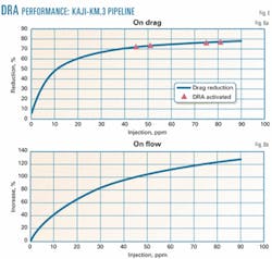
The DRA would be applied at Kaji and booster stations along Kaji-KM.3 pipeline (Fig. 2). DRA injection could increase the Kaji-KM.3 pipeline capacity by more than 90% from its baseline capacity while permitting pipeline-operating pressure to remain within allowable range.
DRA application would allow production of KS field to be accelerated, allowing PTEN to benefit from the domestic market obligation free period and the crude price increment with minimum investment and operating cost.
What is DRA?
DRA consists of chemical agents that reduce or minimize frictional pressure loss caused by the turbulence in the pipeline.1 A DRA does not work in laminar flow regimes because drag reduction occurs by an interaction of the polymer molecules of the DRA with the turbulence formation of the flowing fluid or hydrocarbon.
DRAs are solutions of poly alpha olefins, high-molecular-weight copolymers, and viscous or non-Newtonian fluids that are based on either hydrocarbon (iso-pentane or kerosine) or water solvent.
Reducing pressure loss allows the pipeline operation to be optimized in several ways, such as increasing flow rate in existing pipeline system while maintaining operating pressure, reducing pipeline operating pressure while maintaining total throughput or flow rate, reducing energy and operating cost by eliminating a pump booster station along the pipeline system, and many other applications.
The first use of a DRA in the oil and gas industry was to reduce the pressure loss during pumping of fluids downhole to fracture tight formations. DRA application for crude oil transportation or pipeline system began around 1978 with the first injection into the Trans Alaska Pipeline system.
Currently, DRAs used in oil and products pipelines are themselves hydrocarbons and thus have no effect on refining processes or refined products. Crude oil treated with DRAs on TAPS has been refined without incident. Similarly, crude oil from the Kaji-Semoga field at South Sumatera, which is transported through the Kaji-KM.3 pipeline system treated with a DRA, has been refined without any incident.
Mechanism1-5
In a hydrocarbon stream, the DRA lowers the frictional pressure loss caused by turbulence in the pipeline. Understanding how turbulence is created and why the turbulence could cause a frictional pressure drop in a fluid flow and how DRAs could reduce the turbulence and thus the frictional pressure loss requires a description of the structure of turbulent flow.
In turbulent flow regimes, there are three different zones or layers.
Nearest the pipeline wall is a zone called laminar sublayer. Here, the fluid follows the pipeline flow in a typical laminar flow regime. The increase in point velocity as the point moves away from the wall, is a linear function of the distance from the wall and directly parallel to the wall in the direction of pipe flow. There are no cross flows in this zone.
In the very center of the pipe is the turbulent core zone, the largest region and the one that holds most of the fluid in the pipe. This is the zone of the eddy currents and random motion of turbulent flow. The turbulent core carries all of the flow where variations in point velocity are random and dependent of this distance.
Between the laminar sublayer and turbulent core zones lies the buffer zone. Here, the variation of point velocity with point position is not established. This zone is important because it is here that the turbulence first forms.
Now we will discuss how turbulence is created and why the turbulence could cause a frictional pressure loss in a fluid flow and also how a DRA could reduce the frictional pressure loss caused by the turbulence.
A portion of the laminar sublayer called "streak" will occasionally move up to the buffer zone. Once the streak enters the buffer zone, it will begin to vortex and oscillate, moving faster as it gets closer to the turbulence core. Finally, the streak becomes unstable and breaks up as it throws fluid into the core of the flow. This ejection of fluid in the core is called "turbulent burst" and creates the turbulence in the core. Energy is wasted in different directions causing the drag and pressure loss.
Drag reduction occurs by an interaction of the polymer molecules of the DRA with the turbulence of the flowing fluid. Drag-reducer polymers interfere with the bursting process or inhibit the formation of turbulent burst and prevent the turbulence from being formed or at least reduce the degree of turbulence and, in turn, the drag or pressure loss.
The drag-reducer polymers somehow stretch in the flow, absorb the energy in the streak, and thereby prevent the turbulent burst. As such, DRA polymers are most active in the buffer zone.
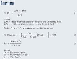
Drag reduction is defined as the increase in pumpability of a fluid caused by the addition of small amounts of an additive (DRA) to the fluid. The effectiveness of a DRA is normally expressed in terms of percent drag reduction (%DR; Equation 1 of the accompanying box).
The reduced frictional pressure drop normally is used to increase flow rate while maintaining pipeline operating pressure that does not exceed the safe pressure limits within the pipeline system.
The relationship between drag reduction and percent flow increase can be estimated with Equation 2.
Equation 1 defines %DR. Equation 2 assumes that frictional pressure drop is proportional to flow rate raised to the 1.8 power, for both treated and untreated fluids, and that the discharge pressure is constant for both the baseline and increased flow rate.
In general terms, the higher the degree of turbulence of the fluid in the pipeline, the higher the drag-reducing performance. Therefore, the drag-reducing performance is increased as the fluid velocity and flow rate increase and as the fluid viscosity and the pipeline diameter decrease, or according to the Reynolds number formula (Equation 3).
The higher the Reynolds number, the higher the drag-reducing performance. The dimensionless Reynolds number indicates the type of flow (laminar, critical, or turbulent) in a pipeline.
A fluid flow with a Reynolds number less than 2,000 is laminar. Turbulent flow has a Reynolds number more than 5000. Between laminar and turbulent flow, there is a critical flow regime with Reynolds number more than 2000 but less than 5000.
Reynolds number is the first indication to determine whether DRA could work in a fluid flowing in a pipeline system. As explained, because DRA could work only in turbulent flow regime, it must have a Reynolds number of more than 5000.
Besides the degree of turbulence, there are some other factors that could affect the performance of DRA. Water cut of crude oil, wax content, and free-gas content (in multiphase flow) are some of these.
As stated, DRAs are solutions of poly alpha olefins, a high-molecular-weight copolymer with either hydrocarbon or water base. High-molecular-weight copolymers, such as poly alpha olefins, are shear sensitive, and drag-reducing performance could be affected when a DRA passes a high-shear-force region in pipeline system, such as Ts, bends, partly open valves, and especially pumps.
The general rule of DRA injection is always to inject the DRA on the discharge side of the pump. And if drag reduction is required along a pipeline system with N pump stations, the DRA must be injected at N points or at every pump station, unless the pump station is by-passed.
KAJI-KM.3 application6-8
The Kaji-Semoga (KS) field, on Rimau block in South Sumatra, Indonesia, began producing in 1997 with initial production around 2,600 bo/d. The initial reservoir study calculated the field's proved reserves at about 77 million bbl with peak production forecast to be about 40,000 bo/d for 1999-2000.
Two pipeline systems were built to deliver the field production from Kaji station, the main oil gathering station, to the Plaju refinery. The first is a twinned 4-in. OD system tied to the Tempino-Plaju pipeline system, operated by Gulf Resources Indonesia, at two selling points, kilometer point (KP) 77 and KP 102.
The second pipeline is an 8-in. OD line tied to PTEN-owned Jene-KM.3 line, with total length about 148 km (92 miles). Along this pipeline, to accommodate 40,000 bo/d of KS field's peak production, two booster pump stations were built in 1999, at Penga- buan and Serdang, increasing capacity to 26,000 bo/d from 18,000 bo/d. The remaining 14,000 bo/d of KS field production was delivered to KP 77 and KP 102.
As the development drilling continued, the KS field reservoir and proven reserves were found to be larger than earlier expected. The field-proven reserves were increased 135 million bbl of oil from 77 million bbl of oil and the field peak production was reforecast to be about 68,000 bo/d for 2001 (as stated in the revised plan of development of March 2000).
Because the crude oil transportation system was set up only to accommodate the previous peak production rate of 40,000 bo/d, adjustments or improvements had to be made in the crude oil transportation system to meet the current peak production rate.
To optimize the Kaji-KM.3 pipeline system, an additional booster was built at Tempirai and began operations in early 2000. With this booster, pipeline capacity increased to 35,000 bo/d from 30,000 bo/d. The flow rate to KP 77 and KP 102 was maintained at 13,000 bo/d, making the total pipeline capacity and KS field delivery at 48,000 bo/d.
In 1999, a study was commissioned to install a new 10-in. OD pipeline from Kaji to Tj. Api-Api, with total length around 120 km and capacity of 35,000 bo/d. This new pipeline was expected to cost about $60 million initial investment and require about 2 years to be completed.
Another option was to build a loop line for each section along Kaji-KM.3 pipeline to increase the pipeline capacity to 48,000 bo/d from 35,000 bo/d. This option would cost about $12 million and take about 18 months to complete.
The disadvantage of these options, besides the high cost of initial investment, was that they would take several years to complete. Hence, PTEN could not accelerate production until the entire project is completed. As a result, the company would lose the opportunity to benefit from the domestic market obligation (DMO) free period, which is an incentives given for new oil and valid only for 60 months from the field's initial production.
PTEN would also lose the opportunity to benefit from the crude price increment, which reached the highest point last year.
An option to use a DRA to optimize the pipeline capacity was brought up in August 1999. The field trial was conducted in September 1999 with the objective of increasing the Kaji-Pengabuan pipeline capacity up to 20% from its baseline. The field trial was successful. The flow increase achieved was 32.15% with 24.5 ppm of DRA injection.
Following the successful field trial, PTEN started injecting the DRA commercially on Oct. 27, 1999, initially only at Kaji injection station and Pengabuan booster station.
By the end of the year, the flow rate from Kaji had reached 30,500 bo/d with total drag-reducer injection rate around 30 gpd. In January 2000, the third booster, Tempirai, was completed and started operation.
In the same month, PTEN installed DRA injection facilities at Serdang booster to increase the flow rate through Kaji-KM.3 pipeline up to 40,000 bo/d to meet the production forecast. Finally, PTEN achieved the 41,000 bo/d flow rate in March 2000 with total DRA injection around 90 gpd.
The DRA's performance later turned out to be much higher than expected. By the end of May 2000, flow rate through Kaji-KM.3 pipeline had reached 42,000 bo/d with total DRA injection around 120 gpd, making total KS field delivery of about 55,000 bo/d (including 13,000 bo/d delivered to KP 77 and KP 102).
By the end of July 2000, the flow rate reached 46,000 bo/d with total DRA injection of about 200 gpd. PTEN finally achieved 50,000 bo/d flow rate through Kaji-KM.3 pipeline in September 2000 with total DRA injection at about 280 gpd and with DRA injection operating cost of about $0.50/bbl increment, making total KS field production and delivery 63,000 bo/d, more than it the 53,000 bo/d forecast for 2000.
With DRA injection, PTEN was able to accelerate KS field production without waiting for the new pipeline or loop line to be completed, with minimum initial investment, because all of the injection facilities such as injection pump and skid, tote tanks, etc., are provided free by the DRA manufacturer, and also low operating cost.
Acceleration of KS field production allowed PTEN to have net share increment about $22 million within 1.5 years (estimated time to develop a loop line).
In September 2000, PTEN shut down one of three booster pump stations and increased the amount of DRA injected at Kaji station to maintain the flow rate through Kaji-KM.3 pipeline at 50,000 bo/d.
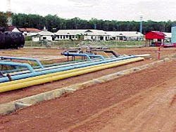
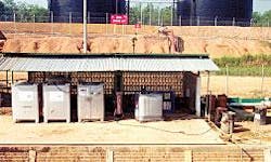
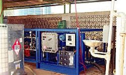
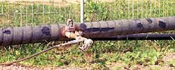
Fig. 3 shows the DRA injection site at the Kaji pump station; Fig. 4, the injection module; and Fig. 5, an injection point port.
With one booster pump station shut down, PTEN could save the operating cost of about $700,000/year. And one booster station being shut down while the flow rate from Kaji station is maintained at 50,000 bo/d means the DRA performance or the flow increase achieved with DRA injection is more than 90% of the base flow rate, with operating cost only $0.65/bbl increment.
As the KS field peak production forecast was stretched to 75-80,000 bo/d, PTEN needed to optimize the crude oil transportation system once again. A new export terminal at Tengguleng and a new 8-in. pipeline from Kaji station to the terminal were built and began operating in early 2001. This new pipeline and terminal handled up to 30,000 bo/d of KS field production.
With additional crude expected from new discovery fields near the KS field, the Kaji station crude transportation system will be expected to handle up to 90,000 bo/d of crude production. As such, it will be necessary to maximize the throughput of all the outlet and pipeline systems.
The maximum flow rate, which could be delivered through Kaji-KM.3 pipeline with DRA injection is 52,000 bo/d, with two booster stations running, and up to 57,000 bo/d with three booster stations running.
Fig. 6 shows the effect of DRA injection on drag (Fig. 6a) and flow (Fig. 6b).
Sangasanga-Balikpapan application
The North Kutai Lama (NKL) field, at Sangasanga, East Kalimantan, is an old oil and gas producer. For many years, there was no exploration and field development in this field. But recently, PTEN conducted a series of 3D seismic surveys and drilled new infill wells. The crude oil production from the new wells was forecast to be around 2,000 bo/d after completion of the development drilling.
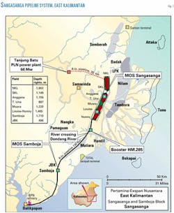
The current total production from Sangasanga area, including the NKL field, is about 4,500 bo/d. The crude oil is transported from the Sangasanga main oil storage (MOS) station to the Balikpapan refinery through a single pipeline system consisting of 6, 8, and 10 in. OD pipelines with a total length of about 100 km (Fig. 7).
Along this pipeline, there is a booster pump station and Samboja main oil storage station, which receive crude oil from MOS Sangasanga and the Samboja field. The maximum flow rate from MOS Samboja is only about 5,000 bo/d due to limited pipeline maximum operating pressure.
Due to pipeline aging, the maximum allowable operating pressure is only about 300 psig from the MOS Sangasanga to the booster pump station and about 175 pisg from the booster pump station to the MOS Samboja. From MOS Samboja to the Balikpapan refinery, the pipeline operating pressure is limited to 115 psig maximum. If the pump discharge pressure exceeds the pipeline MAOP, leaks could occur at several locations along the pipeline.
To deliver existing plus additional crude production, total about 7,000 bo/d at peak rate, some options are currently being discussed. Meanwhile, the new wells in NKL field will start to produce around 500-1,000 bo/d.
To prevent stock build up at MOS Sangasanga, it will be necessary to deliver this additional crude. It is possible to transfer 500-1,000 bo/d of crude from Sangasanga to Samboja, but not from Samboja to Balikpapan due to limited pipeline MAOP.
The fastest option or solution is the use of a DRA. To determine whether DRA could be applied, PTEN conducted a field trial at MOS Samboja in March 2001. Based on the performance prediction, PTEN started the DRA injection at 24-25 gpd. The line filling period is 48-50 hr due to the long pipeline length and low flow rate.
After the line fill period, the flow rate started to increase from 5,100 bo/d average to 7,005 bo/d maximum at the same 115-psig operating pressure. The trial objective, to get 7,000 bo/d at the same operating pressure, was achieved.
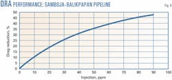
The DR% was calculated to be 45.59%, while the flow increased percent was calculated to be 40.28% from the original baseline with 24 gpd or 81.798 ppm (vol) of DRA injection (Fig. 8).
After the successful trial, PTEN started to deliver the additional crude from NKL field to prevent stock build up at MOS Sangasanga.
The maximum rate from Samboja reached almost 6,000 bo/d with only 12 gpd of DRA injection. The pipeline operating pressure could be maintained within safety limit or still less than 115 psig. The operating cost for DRA injection at Samboja is only $0.39/bbl increment.
Success
The DRA application on Kaji-KM.3 pipeline is successful and working well. With DRA injection, PTEN optimized its pipeline capacity and increased throughput up to 90% from its baseline, allowing delivery of more crude oil from Kaji station and acceleration of the Kaji-Semoga field production.
The company was able to accelerate revenue through the DMO free incentive and crude price increment with net share increment about $22 million within 18 months.
Additional advantages of the DRA application on Kaji-KM.3 pipeline are the energy and operating-cost savings from shutting down one the three booster pump stations while maintaining throughput at 50,000 bo/d.
The other DRA application on Samboja–Balikpapan pipeline is also successful. With DRA injection, PTEN could deliver the excess or additional crude production from NKL field to prevent stock build up at MOS Sangasanga with low operating cost and minimum initial investment cost.
References
- Lester, C.B., OGJ, Feb. 4, 1985, p. 51.
- Lester, C.B., OGJ, Mar. 4, 1985, p. 107.
- Seyer, F.A., and Metzner, A.B., "Turbulence Phenomena in Drag Reducing System," AIChE Journal, May 1969, pp. 426-34.
- "Drag Reduction," Encyclopedia of Polymer Science and Engineering, second edition, Vol. 5, pp. 129-51; New York: John Wiley & Sons Inc., 1986.
- Denys, R., Pipeline Technology, Proc. of the 2nd International Pipeline Conference, Ostend, Belgium, Sept. 11-14, 1995, pp. 143-49.
- Kaji Semoga Reservoir Simulation Study, final report, Reservoir Engineering Department, PT Exspan Nusantara, Jakarta, 2000.
- Kaji Semoga Field Plan of Development (revised), PT Exspan Nusantara, Jakarata, 2000.
- Daily Pumping Report from Kaji Station to KM.3 via Booster, PT Exspan Nusantara, Jakrata, 1999-2001.
Based on presentation to IATMI (Society of Indonesian Petroleum Engineers) National Symposium, Oct. 1-5, 2001, Yogyakarta, Indonesia.
The author
Indra Prasetyo is the facilities engineer for PT Exspan Nusantara, Indonesia, joining its facilities and design engineering department to develop mechanical and pipeline facilities after graduating in 1998 with a BS in mechanical engineering from Trisakti University, Jakarta.
