Research aims at lowering costs to make new discoveries economic
About this series…This article begins a series of occasional articles that will comprise a "dialogue" among industry experts and professionals on some of the major technological issues over the coming years in the laying and maintaining of natural gas pipelines. In the weeks and months to come, others involved in pipeline research and development will comment on some of the issues raised here and will raise additional topics for others to address.
Major gas producing companies are investing heavily in technological developments to reduce the cost of energy delivery. These competing technologies include:
- New design methods, materials, welding, and construction practices for large-diameter pipelines.
- Lower cost LNG transportation.
- Conversion of gas to liquids.
- Generation of high DC-voltage electricity for long-distance transportation.
Over the next decade, operators will be considering onshore developments that will involve installation of tens of billions of dollars of pipeline infrastructure. In several cases, the cost of exporting the product will determine the viability of the upstream production facilities so that some projects may only progress if the costs of getting the gas to markets can be substantially reduced.
A number of massive pipeline projects are planned or under way around the world to meet this demand for natural gas. One example is the increased likelihood of pipeline systems to transport gas from northern Canada and Alaska to the Lower 48 states to meet the ever-increasing US demand for energy.
It seems clear that the world's pipeline systems will form an integral part of energy delivery for many decades to come.
The international pipeline industry has risen to the challenge of reducing pipeline capital expenditures with new, more rational design methods, very high-strength line pipe, innovative welding methods, and advances in construction processes and equipment underway.
Perhaps of much greater importance is the increasing willingness for operators, contractors, suppliers, and manufacturers to co-operate closely in seeking alternatives in performing pipeline projects.
Cost-reduction project
The BP Pipeline Cost Reduction technology project is a group of highly focused development activities seeking a significant reduction in pipeline capital expenditure by technology innovation.
The work covers advances in design, materials, welding, construction, and operations that will have benefit in reducing capital expenditure while maintaining company expectations on operational excellence, safety, and environmental protection. All the technology items discussed in the remainder of this article are part of the research and development work under the BP PCR project.
The following sections will speculate on where current pipeline technology activities will lead. These sections assume that construction is about to begin on a 1,000 mile, 48-in. pipeline in an arid environment (typically North Africa) during 2006 and consider the technology that would be available if current technological developments are taken through to field application. Most of the technology items discussed below are under development and should be field proven by 2006. Some items are still at the concept stage and so are speculative.
Design
The traditional approach to pipeline design is to determine pipeline wall thickness by use of a design factor selected to provide an increase in wall thickness in areas of increased population density. Although pipelines designed this way are demonstrably safer, the method fails to address the real reasons pipelines fail in operation nor does it give a quantitative understanding of the level of conservatism inherent in the design.
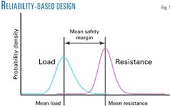
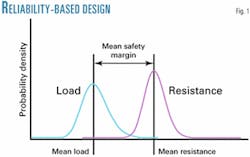
Reliability-based design techniques provide the opportunity for the operator to have a complete understanding of the vulnerability of the pipeline to such failure mechanisms as external impact, corrosion, or ground movements and the influence of a rational inspection and maintenance management system on operational reliability.
The methods allow the pipeline engineer to design for the actual failure mechanisms anticipated and give the opportunity to optimize the wall thickness required. Although it has been used to benefit offshore, the added implications of consequence and risk for onshore pipelines makes the development of target reliabilities of greater concern and forces the engineer to look closely at the societal and environmental impact of the pipeline within the design process.1 2 3
Guidelines and software to apply the techniques were produced in 2001 by C-FER Technologies, Edmonton, and funded by BP Exploration Inc. and TransCanada PipeLines Ltd., and are available to the industry (Fig. 1).
Probabilistic-based methods allow design options to be fully evaluated on a risk or reliability basis. The methods allow the engineer to account fully for uncertainty in data on line pipe material properties, ground conditions, and other variables. What is learned could be used to justify use of design factors that are higher than current practice by fully evaluating the influence of all potential failure modes on the reliability of a given pipeline.
Section valves
Historically, most pipeline codes and regulations impose arbitrary spacing requirements for section valves on gas transmission pipelines that are independent of operating pressure or diameter. Codes that have specific valve-spacing requirements are generally derived from American Society of Mechanical Engineers (ASME) code B31.8, which was developed more than 40 years ago, with valve spacing linked to class location (population density). For a Class 1 area, the prescribed valve spacing is 20 miles, reducing to 5 miles in Class 4 areas to protect an increased population density.
The rationale behind ASME B31.8's valve-spacing requirements has no scientific basis.1 The prescribed spacing is intuitive rather than based on safety considerations and could be safely increased. The code requirements were developed by consensus and have become accepted practice by industry and regulatory authorities.
Section valves do not prevent incidents from occurring, and thus their originally intended role must have been to reduce the consequences of an incident. An industry-sponsored study1 concluded that injuries and fatalities are related not to the spacing of the valves but to the proximity of individuals to the point of release.
The review of the incident data indicates that in more than 98% of the incidents involving injuries and fatalities, the initial release of gas or ignition was the cause.
Design for the most probable failure mechanisms and a rigorous operational integrity-management system are essential to avoid such incidents.
Development of a technical and scientifically based model for optimum spacing for block valves requires consideration of the following:
- Operational and maintenance constraints.
- Cost effectiveness of block-valve spacing.
- Conservation of gas for economic and environmental reasons.
- Frequency of block-valve operations.
- Probability of valves failing to seal.
Increased valve spacing is currently proposed in several BP pipeline projects around the world, and it is therefore anticipated that spacing in excess of 40 miles for Class 1 areas will be proposed for future pipeline projects. The valve spacing at the other class locations will be decided on a rational basis related to the actual societal and environmental conditions and with due regard to the mentioned considerations.
Materials
The simple concept of gas being compressed under increased pressure offers an opportunity to reduce capital expenditure on a new pipeline system.
With a few exceptions, onshore gas pipeline systems tend to operate with maximum operating pressures in the range of from 1,000 to 1,500 psi. Increasing the pressure to 2,000 psi, or even 2,500 psi, will reduce the required diameter of a pipeline. A pipeline of 48 in. OD at 1,450 psi could be reduced to 40 in. OD at 2,500 psi; but nothing is ever that simple.
The disadvantage of designing for higher-pressure operation for a given diameter is that wall thickness will increase, ultimately introducing difficulties in line pipe manufacture and construction operations.
Over the last decade, while API 5L X-80 line pipe has been accepted in the UK and Canada, line pipe suppliers and operators have been engaged in developing an even higher strength material—X-100. It has minimum yield strength of 100,000 psi allowing a wall thickness amenable to manufacture and welding to be used for high-design pressure, as shown in the accompanying box on this page for a 48-in. pipeline designed for 2,500 psi under a design factor of 0.8.
X-100 material grade has experienced the most comprehensive development and test program of any line pipe material produced to date with five major international pipe mills providing several generations of prototype line pipe over a 10-year period for characterization, field welding, and bending trials variously funded by the operators BP Exploration, TransCanada, Royal Dutch/Shell Group, BG Group PLC, and the research group European Pipeline Research Group (EPRG).5-8
The material has been subjected to a variety of manual and mechanized gas metal-arc welding (GMAW) procedures for girth welds, tie-ins, and repairs. Centro Sviluppo Materiali and Advantica Technologies have completed group sponsored full-scale burst tests to investigate the material's inherent resistance to running ductile fractures. It is anticipated that X-100 line pipe and operations of up to 2,500 psi will be in pipeline design by 2006.
Welding
Gas-metal-arc welding is the backbone of the pipeline construction industry, and it is anticipated that it will still dominate girth welding on pipelines into 2006. The GMAW process, however, is currently undergoing a transformation to offer quicker welds with much less equipment in the field.
Tandem GMAW differs from conventional GMAW by having two welding wires passed through the same welding torch. A single torch with two contact tips is used to feed both wires into a single weld pool.
Over the last few years Cranfield University in the UK has developed a tandem GMAW torch specifically for use with narrow gap weld preparations utilized in pipeline welding. The process provides high deposition rates and welding speeds two to three times faster than conventional mechanized pipeline welding.
The weld metal microstructure and metallurgical properties are similar to conventional mechanized pipeline welds.
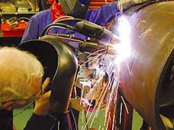
A further development from this is the Cranfield Automated Pipe welding system (CAPS).10 This is an automated gas-shielded metal arc process that employs two tandem-welding torches per carriage. The high speed of the tandem process is retained and two passes are deposited simultaneously.
The effect is a significant reduction in the number of welding stations required to complete a given number of weld's per day and leads to major savings in labor and equipment costs.
For one large diameter pipeline in BP's future portfolio, it is estimated that the use of CAPS could reduce the cost of the pipeline construction (alignment, welding, non-destructive testing or NDT, and coating) by 25% with a total capital expenditure savings of about 5%.
Termed "Dual-tandem GMAW," the carriage is fitted with a sensor-based control system, removing the need for a skilled operator to monitor the weld continuously (Fig. 2). A laser camera seam-tracking system has been incorporated with the welding bug to ensure accurate joint tracking at high travel speeds, typically 4 to 5 fpm.
Funded by BP Exploration and TransCanada, Cranfield University is developing a prototype production dual-tandem GMAW welding system for field trials in Canada during first quarter 2003. The system is primarily developed for the new generation of large diameter, high-strength gas transmission pipelines.
It is anticipated that the dual-tandem GMAW welding process would be used for a pipeline with a multi-head internal welding machine for the root pass and automated ultrasonic testing used for weld inspection.
Construction equipment
There are currently proposals being considered by members of the International Pipe Line and Offshore Contractors Association (IPLOCA) for formation of shared construction equipment pools at strategic locations around the world.9
Each pool would allow equipment users to reduce mobilization costs through access to fully maintained equipment local to their work sites. It also enables equipment owners to utilize major equipment items more fully.
It would be accessed through a website that would provide information on the availability of equipment in the vicinity of the planned work site as well as the operational status of individual pieces of equipment. The independently managed equipment pools would provide a full maintenance service on all equipment.
Although the largest cost element of a typical onshore pipeline development is the construction process, it is surprising that until 2000 it has been largely ignored in the major pipeline research activities funded by the leading industrial organizations. During 2000-01, BP Exploration funded a program of activities with MG Bennett & Assoc., UK, then Rahco International Inc., Spokane, Wash., to explore the feasibility of bringing the efficiencies associated with offshore pipelay to onshore construction.
This work concluded with the detail design of a construction train consisting of several modules based on a common work platform and capable of handling up to 52-in. OD pipe and operating in such extreme environments as the Alaskan winters and Saharan summers.
The exercise clearly demonstrated that there is at least one viable alternative for constructing onshore pipelines over the traditional multi-vehicle approach; Fig. 3 presents two concepts of future construction equipment configurations.
The exercise provided the basis for BP Exploration and IPLOCA to hold workshops in the UK during 2001-02 involving operators, contractors, and equipment manufacturers to determine the industry view of possible development opportunities. There is now a concerted effort to bring all participants together in a joint-industry-funded activity directly to address development and innovation in pipeline construction equipment and processes.
BP Exploration is working with other major industrial companies to develop the scope of work and find funding for a comprehensive range of potential development items.11 12 Several of these opportunities are briefly discussed presently.
Excluding trenching, the rate of progress of the onshore pipelay spread depends upon the speed of the welding process. More detailed assessment indicates that it is the speed of the root pass. Simulation of the process has shown that the handling and alignment of the pipe in preparation for the root pass dominates the operation.
The conclusion is that it is impossible to realize fully the capability of the developing welding processes without quickening the handling and alignment of the pipe.
The proposed development is for a pipeline alignment vehicle capable of picking up straight or field-bent pipe from cribbing and skidding.
Working with an enhanced line-up clamp, the vehicle aligns the joint of pipe accurately for the root pass. Such a vehicle would introduce the possibility of accepting pipe directly from a transportation vehicle thereby avoiding stringing entirely.
Pipeline operations in arctic environments tend to be performed in the winter months above frozen soils, often on ice roads. The pipeline crew must tolerate temperatures as cold as -40° F. often combined with wind chill.
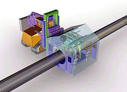
A desire to reduce the environmental influence on the personnel combined with the concept of a welding cabin specifically designed to allow the rapid deployment of automatic welding processes have led to the concept of an environmentally controlled cabin deployed hydraulically off a common work platform for automatic welding (AUT) and field-coating operations.
The vehicle would be designed to allow the crew to remain in the vehicle during move up, protect the occupants from the environment (whether it be arctic or hot), and allow quicker deployment of the welding, inspection, and coating equipment. The vehicle would carry power generation, power sources, gases, and all services necessary to support the particular operation (Fig. 4).
The cabin is a dedicated support vehicle for tie-in welding and inspection and incorporates a handling and alignment system and a mechanized welding process with automated ultrasonic testing equipment.
Additional items identified included improve cribbing-skidding systems; pipeline beveling machine and carrier vehicle with built-in bevel inspection; and improved internal line-up clamps
The momentum now developed through open dialogue has spurred some pipeline equipment manufacturers to perform conceptual design work of new equipment in advance of the proposed joint industry project increasing the likelihood that it will be field proven in time for use on a pipeline in 2006.
Corrosion coatings
A full understanding of the ability of commercially available pipeline corrosion coatings to withstand damage has allowed a change of the common practice of importing sand or other fine material for bedding and padding.
Damage to pipeline coatings can generally occur in three ways:
- Impact damage as padding materials are dropped on to the pipe.
- Penetration of the coating as the pipe bears down on the bedding material under the combined weight of the backfill and hydrotest water.
- Abrasion of the coating as the pipe expands and contracts in the axial direction during service due to variations in product temperature.
Small and large-scale tests performed by Advantica Technologies, UK, for BP Exploration and BG Group's Transco in 2001-02 demonstrated that many common pipeline coatings and field joint protection systems are far more robust than previously thought.13 14 A methodology has been developed that determines the maximum tolerable size of bedding and padding materials for different external coatings to allow the lowest cost combination of coating and bedding material to be determined.
It is anticipated that the cost of specifying a more damage-resistant coating will be more than offset by a reduction in the cost and logistics for obtaining fine padding and bedding, resulting in a net cost saving to a pipeline project.
The approach has been applied to BP's Shah Deniz gas-export pipeline to reduce the amount of spoil crushing required in rocky terrain to produce suitable bedding and padding material. The spoil size requirement was increased from 6 mm to 22 mm for a three-layer polyethylene coating material.
Instead of using one coating for the entire length of our pipeline in 2006, the knowledge developed by the BP Exploration and Transco test program would allow the most appropriate coatings to be used for each section along the pipeline to cater for the local ground conditions and minimize the need for imported padding and bedding materials.
Horizontal drilling
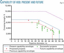
Fig. 5 shows the experience envelope for horizontal directional drilling (HDD) up to 2002. The experience limit covers a series of 56-in. pipeline crossings including the 2,960 ft crossing of the Kuban River for the onshore section of the Blue Stream pipeline in Russia. One US contractor has expressed the gradual increase in his capability as 2,000 ft of 12-in. in 1980, 3,500 ft of 24–in. in 1990, and 5,000 ft of 36-in. in 2000.
Discussions between the BP Pipeline Cost Reduction project and a number of HDD contractors indicate that, assuming good ground conditions, crossing lengths of up to 10,000 ft and diameters of up to 60-in. are feasible.
Internal BP discussions on potential future development work for the Pipeline Cost Reduction project suggested that advantage may be gained from use of a highly mobile, rapidly deployed horizontal drilling rig for the multitude of short crossings on many pipeline routes.
Subject to funding availability, this will be included in the 2003 work agenda.
Will it happen?
When the Pipeline Cost Reduction project started in 1998, the pipeline industry seemed reluctant to take up development issues. Although there was development underway within organizations, striving for commercial advantage prevented meaningful co-operation.
Now, there is now a climate of change and considerable momentum has been achieved across the entire industry. Many of the technology items discussed here will likely become established practice in coming years.
More than 50 operators, contractor, supply, and manufacturing companies are involved with current pipeline development work, often at their own expense. Whereas in the past, the leading industrial and research organizations have tended to be inward looking, they are now having dialogue with organizations with contrasting constitutions and membership.
The Australian Pipeline Industries Association, EPRG, and Pipeline Research Council International have agreed to a tripartite working agreement on the sharing of information. IPLOCA has talked about possible cooperation on common issues with the operator-dominated EPRG and the European Gas Research Group.
Line pipe suppliers are co-operating with operator and research organizations with free supply of development grades of line pipe for material testing and field demonstration. Researchers are openly publishing their results to promote and maintain dialogue.
The technology items mentioned here are only a glimpse of the opportunities under development for the onshore pipeline industry and represent those that could realistically be implemented in the relatively short timescale considered here.
Extending the horizon 10 years encompasses many other technologies that could benefit this industry. For example, the GMAW welding process may give way to Nd: YAG or diode laser hybrid systems in the coming years. Composite reinforced line pipe allowing high-grade performance from low-grade steel liners is at a late stage of development.
References
- Zimmerman, T.J.E., Cosham, A., Hopkins, P., and Sanderson, N., "Can Limit States Design be Used to Design a Pipeline Above 80% SMYS," OMAE, Lisbon, 1998.
- Zimmerman, T.J.E., Nessim, M., McLamb, M., Glover, A., Rothwell, B., amd Zhou, J., "Target Reliability Levels for Onshore Pipelines," Proceedings of the International Pipeline Conference, Sept. 30-Oct. 4, 2002, Calgary.
- Lamb, M., and Zimmerman, T.J.E., "The Decision Process for the Use of Risk-Based Design for Onshore Pipelines," Onshore Pipeline Cost Reduction Conference, Amsterdam, Apr. 3-5, 2000.
- Eiber, R., McGehee, W.B., Hopkins, P., Diggory, I., Goodfellow, G., Baldwin, T.R., and McHugh, D.R., "Valve Spacing Basis for Gas Transmission Pipelines," PRC International, PR-249-9728, September 1998.
- Hudson, M.G., Blackman, S.A., Hammond, J., and Dorling, D.V., "Girth welding of X-100 pipeline steels," Proceedings of the International Pipeline Conference, Sept. 30-Oct. 4, 2002, Calgary.
- Millwood, N.A., Sanderson, N., and Hammond, J., " Design and Construction of Pipelines in Ultra-High Strength Line pipe," Onshore Pipeline Cost Reduction Conference, Amsterdam, Apr. 3-5, 2000.
- Ohm, R.K., Martin, J.T., and Orzessek, K.M., "Characterisation of Ultra-High Strength Line Pipe," Pipeline Technology Conference, Brugge, Belgium, May 21-24, 2000.
- Fu, B., Millwood, N.A., Vu, D.Q., Matthews, S., and Jacobs, M. "Failure Behaviour of Ultra-High Strength Line Pipe," Pipeline Technology Conference, Brugge, Belgium, May 21-24, 2000.
- Potkamp, G., "A Sequal to the Presentation in Salzburg," IPLOCA Winter Newsletter 2001.
- Blackman, S.A., Dorling, D.V., and Howard, R., "High-speed tandem GMAW for Pipeline Welding," Proceedings of the International Pipeline Conference, Sept. 30-Oct. 4, 2002, Calgary.
- Sanderson, N., and Jammes, G., "Security of European Energy Pipeline Infrastructure," Expression of Interest for the European Commission 6th Framework Programme for Research, June 2002.
- Brown, D., "Development of Pipeline Construction Vehicles with Automatic Welding," IPLOCA Spring Newsletter 2002.
- Thompson, I., Espiner, R., and Barnett, J., "Coatings and Backfill System Optimisation," Proceedings of the International Pipeline Conference, Sept. 30-Oct. 4, 2002, Calgary.
- Clough, N., Schofield, R., and Corbally, J., "The Buried Pipeline: An Engineered Approach," Onshore Pipeline Cost Reduction Conference, Amsterdam, Apr. 3-2, 2002.
The author
Norman Sanderson ([email protected]) has been project manager of the Pipeline Cost Reduction Technology project in BP Exploration since 1998. Working for both owner and contracting companies, he is a chartered mechanical engineer with extensive pipeline experience in the oil and gas and petrochemical industries over the last 33 years. He holds a PhD in applied mechanics from the University of Manchester Institute of Science and Technology.
