LNG liquefaction technologies move toward greater efficiencies, lower emissions
This article is the third in a series that began last week and concludes next week.
The LNG value chain has shown outstanding safety, reliability, and environmental protection performance for more than 35 years. These standards are becoming even more important today.
Design of several new LNG liquefaction plants now requires higher efficiencies and lower CO2 emissions as LNG plant design continues to evolve in response to new challenges.
A couple of new LNG projects have incorporated high-efficiency aero-derivative gas turbine drivers into their design, one plant design is planning to generate steam from the exhaust of gas turbine drives for driving a steam turbine, plans are made for reinjecting CO2 that is produced with natural gas into aquifers, and the use of more-efficient gas and liquid expanders is being considered.
Expansion pace
International LNG trade went through a rapid expansion in the second half of the 1990s. Ten new LNG trains in five new grassroots liquefaction plants came on stream, representing more than 30 million tonnes/year (mty) of new capacity. Most of this has been sold under traditional long-term, take-or-pay contracts that have dominated the LNG trade.
This new LNG is being delivered to the largest traditional market, Japan, to the fast-expanding Korean market, to new and existing markets in the Pacific, and to newly resurgent Atlantic Basin markets.
Most surprising perhaps has been the increased interest in LNG in the US market, with a new terminal operating in Puerto Rico, reactivation of two East Coast mothballed receiving terminals, expansion plans in all terminals, and announced plans for 10 or more new grassroots terminals (OGJ, Aug. 12, 2002, p. 56).
LNG liquefaction capacity continues to be added rapidly. An expansion train at the Atlantic LNG plant in Trinidad is being brought on stream this summer, and the third train at ALNG is following it.
There are several LNG trains in various stages of engineering and construction in Trinidad, Nigeria, Malaysia, Australia, Qatar, Egypt, and Norway. Many other projects are in planning stages (OGJ, Apr. 22, 2002, p. 74).
Liquefaction plants have always been designed along the "train" concept. Depending on gas reserves and markets, some new plants start up with a single train, and most eventually have several parallel process trains.
Early on, small-size LNG trains matched smaller market demands and fit available equipment capabilities throughout the LNG value chain, which also includes LNG carriers and storage facilities. Each process train includes gas treating, dehydration, mercury removal, refrigeration, heavy hydrocarbon removal, and LNG production and transfer equipment.
The trains are supplied by outside utilities (such as electric power, cooling water, instrument air, etc.), but each is in effect a standalone process plant. It can be shut down without affecting operations at adjacent trains.1
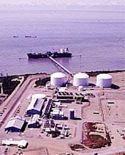
Bechtel Corp. built Phillips Petroleum Co.'s Kenai, Alas., plant (Fig. 1), which pioneered the Pacific LNG trade in 1969. Subsequent debottlenecking has increased the plant's capacity to 1.5 mty.
The plant was the first to use gas turbines to drive LNG refrigeration compressors. It also featured the "two-trains-in-one" reliability concept: Two identical parallel compressor strings are used for each refrigeration service.
This design concept has allowed the plant to operate at more than 95% availability for more than 30 years. The rest of the plant consists of a single train of gas treating, heat exchangers, and liquefaction equipment.
The plant was designed as a simple yet highly reliable gas plant ("gas plant design philosophy") rather than as an expensive petrochemical facility.
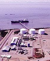
The larger capacity Atlantic LNG Co.'s Trinidad plant Train 1, started up in 1999, is recent reconfirmation of this design philosophy (Fig. 2).3 Train 1 has set a new standard in the LNG industry for low cost and for short schedule, as benchmarked by Independent Project Analysis Inc., Ashburn, Va., a consultancy specializing in project benchmarking (Fig. 3).2
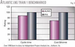
ALNG Train 1 has operated for 3 years and shown that in addition to its cost-effective design, it has achieved an average on stream factor in excess of 95%. Cost-effective design philosophy has been applied to all aspects of the plant, not only the liquefaction section.
Train 1 is currently being expanded and two additional trains are under construction. Planning is under way for additional capacity.
The key principles that have guided LNG plant design have always been:
- Safety, health, and environmental protection.
- Reliability and high stream factor.
- Fitness for purpose, cost, and economics.
Train size trends
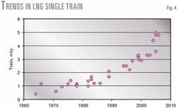
LNG train capacities have been increasing steadily (Fig. 4).
Many factors affect the choice of optimal train size for an LNG project:1
- Long-term gas deliverability from the field and optimal field management.
- Market demand and LNG delivery buildup profile.
- Overall optimization of production, storage, and shipping logistics along the LNG value chain.
- Available proven equipment size.
- Potential capital cost savings.
- Operational flexibility, reliability, and maintenance.
Single-train size has increased to 1-1.5 mty during the 1970s and 1980s from 0.5-1 mty in the early days of LNG. Typical train size has quickly grown from 2 mty in 1990 to 3-4.5 mty today, and trains of more than 5 mty capacities are being considered by several projects.
LNG plants have traditionally been built to satisfy long-term contracts. A typical single gas contract may vary from less than 0.5 mty to more than 3 mty, but an LNG project developer can combine several such commitments to create a larger blocks of demand.
There has been a gradually increasing trend of acceptance of larger equipment sizes for LNG trains. This has been matched by a gradual increase in LNG storage tank size. Early tank designs were usually smaller than 40,000 cu m. Tanks ranging in size between 100,000 and 140,000 cu m were common in new plants of the 1990s, while more recently aboveground tanks with capacities of 180,000 cu m have been built and 200,000 cu m have been designed and proposed. Future designs may include still larger tanks.
The critical components of an LNG train that may be limited in size are mechanical drivers, compressors, heat exchangers, vessels, valves, and piping.
Gas turbines are now commonly used as mechanical drivers in LNG plants. Steam turbines were used in some earlier designs and may be making a comeback in new high-efficiency designs when integrated with heat recovery and steam generation from gas-turbine exhaust.
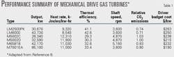
Table 1 shows some of the most common gas turbines considered for LNG use. They can be broadly categorized as heavy-duty industrial types ("frame") and industrial aero-derivatives, characterized by their lightweight and higher efficiency.
To date, no aero-derivative types have been used in a baseload LNG plant, but several recently announced projects are planning to use them.
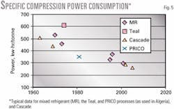
The evolution in compressor design has been coupled with advances in turbine drivers. Together, these driver-compressor combinations have contributed to a steady decrease in specific power requirement for liquefying natural gas and hence to improved efficiency. Fig. 5 illustrates this trend.4 5
Power requirements for the cascade process decreased from 509 kw-hr/tonne for the world's first base-load LNG plant at Camel in 1963 to 440 kw-hr/tonne in Kenai (1969) to the current range of 250 to 330 kw-hr/tonne.5 Efficiencies determined in a Phillips-Bechtel study are in the range of 260 to 290 kw-hr/tonne. Fig. 5 shows similar reductions for other processes.
This is not surprising because all liquefaction processes use similar (or the same) gas turbines and compressors. It should be noted that this comparison is only approximate because different plants have different design bases, such as different ambient temperatures, cooling-water temperatures, natural gas composition, economic criteria, etc.
While increasing driver and compressor size usually results in improved efficiency and lower costs, care needs to be taken in designing, procuring, and constructing the rest of the plant in a cost-efficient manner. Heat exchangers, vessels, pipes, valves, and control systems need to be scaled up properly to avoid costly, one-of-kind equipment that is pushing the limits of acceptable design and "off-the-shelf" low cost.
Driver, compressor configurations
GE Frame 5 industrial gas turbines have well served Phillips' Optimized Cascade LNG process, as well as other processes. Phillips' Kenai liquefaction plant was started up in 1969 with single-shaft Frame 5 drivers and has been operated since without a single shipment missed or delayed. Two-shaft gas turbine machines were introduced in the late 1970s.
Although the single-shaft machine served its purpose and continues to do so in power-generation service, split-shaft machines offer greater operating flexibility. Atlantic LNG's facility in Trinidad and Tobago is equipped with split-shaft Frame 5 gas turbines. This plant has operated well since 1999.
Single-train LNG production demands are currently ranging from 1.5 mty to more than 5 mty-a range which remains a good fit for Frame 5 turbine drivers. It is possible, however, to use other drivers such as larger Frame machines and aero-derivatives such as the LM2500 and LM6000. Different driver configurations are being studied by the Phillips-Bechtel LNG Product Development Center.
This center is the focal point of the cooperative effort to improve the overall LNG product in all areas including the Optimized Cascade process. The center is responsible for improving the product by executing various process- engineering optimization studies, value engineering, work-processes automation, and designs. The center is responsible for ensuring the Optimized Cascade process and resulting facility design remain competitive. A competitive product is measured in terms of cost, schedule, reliability, economic operability, and client satisfaction of resulting product.
Phillips' process is known for its "two-trains-in-one" dual-refrigeration operating concept, which provides maximum operating flexibility of the refrigeration process and thus the plant as a whole.
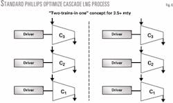
This configuration is only an option, however, that is available should the client desire a more robust design over the single-train arrangement. Fig. 6 presents the dual-train concept. This arrangement is applicable for all other turbine drivers such as the LM2500+, LM6000, and Frame 6.
Table 1 presents performance data for gas turbines currently in use or those that can be used with Phillips' process.9
Liquid expanders
Until the acceptance of turboexpanders, NGLs were extracted by means of lean-oil adsorption processes and inefficient cryogenic plants, the latter operating under the Joule-Thomson principal. Simply stated, this principal involves the expansion of a gas across a valve that results in a temperature decrease for a given pressure change.
The change in pressure (high to low) is a form of useful work that can be used to drive electric generators, pumps, compressors, etc. The turbo-expander technology optimizes the expansion process to achieve much lower temperature changes for a given pressure change while recovering useful energy.
Most natural gas processing plants by the 1970s had incorporated turbo-expander technology as a means efficiently to extract ethane, propane, and butane from associated (oil-condensate) and nonassociated reservoirs (primarily gas).
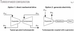
Fig. 7 presents two of the most common configurations for which the turboexpander is utilized.
Option 1 is the most typical of all gas plants; Option 2 occurs in areas outside the upstream business. Either option is acceptable, the installation configuration depending upon process needs of the facility and operator preference.
Turboexpander manufacturers contribute most of the experience within upstream natural gas processing facilities where feed streams are typically near hydrocarbon dew point.
There are facilities operating today, however, in critical and super critical (dense phase) environments. Examples include Duke Energy Field Services' Giddings, Tex., plant and the Aux Sable straddle plant south of Chicago. Duke Energy Field Services is a joint venture between Duke Energy Co. and Phillips Petroleum Co.
The Giddings plant was commissioned in 1982 with a base design of 75 MMscfd at 82-mole % ethane recovery. In 1991, Phillips proposed debottlenecking the plant to accommodate growth of the Austin Chalk development.
The debottlenecking exercise required redesign of the Mafi-Trench Frame 2.5 turboexpander to retain the 82-mole % ethane recovery without major revamp of the cryogenic plant. The debottlenecking recommendations were implemented and the redesign expander commissioned in 1992.
The plant's turboexpander redesign was based on an inlet, gas pressure and temperature of 905 psia and -63° F. These operating parameters place the inlet feed stream of the expander above the critical pressure (Pc= 888 psia) but below the critical temperature (Tc= -78° F.). Actual operations of the expander saw on average an inlet pressure and temperature of 840 psig and -61° F. while achieving better-than-design ethane recovery.
In 1999, the expander was repaired following damage during an operational upset. The plant took this opportunity to have the expander and compressor wheels fine-tuned to improve efficiency further.
The Giddings plant has since replaced its amine gas treater, resulting in a more-suitable gas stream for deep ethane recovery, exceeding 82 mole %. A further modification within the facility residue-gas circuit has provided the opportunity to adjust the expander operating parameters further.
On average, the expander can see 940 psia (±10 psi) and -64° F., both above critical. Operation in the critical augments ethane and propane recovery.
Turboexpander operations above the critical point are not new.
The Aux Sable straddle plant in south Chicago operates under dense-phase conditions. It was designed with two expander extraction trains, each capable of processing 1.05 bcfd (2.10 bcfd total) with an ultimate recovery of 94% ethane, and 100% propane and heavier components.
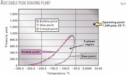
An expander inlet pressure of 1,270 psia and 20° F. places the feed stream well above the P-T critical (OGJ, July 2, 2001, p. 48). Fig. 8, although inexact, provides a meaningful representation of an expander operating under dense-phase conditions. Who would have thought an expander could operate under such conditions?
Bubblepoint application?
Turbo-expander technology has more than proven itself in gas-phase environments. A question being addressed by Phillips-Bechtel alliance and others, however, is whether turbo-expanders can be used in bubble-point service.
Mechanical expansion of a liquid at bubble point or subcooled conditions is not new. Ebara International Corp., Rock Hill, SC, designed and tested the first prototype turbine expander for National Helium Corp., Liberal, Kan., in June 1989. Unlike the turboexpander, the Ebara expander was a four-stage, vertical cryogenic liquid turbine.6
A first-generation liquid turbine expander was commercially produced for MLNG-Dua, Bintulu, Malaysia, in July 1992. These expanders were equipped with 800-kw induction motors that were coupled in the vertical to the expander turbine shaft. This design was large and unreliable.
Ebara International has developed a second-generation liquid turbine that is similar but more efficient than the first-generation turbine built for Malaysia LNG. The second-generation LNG turbine expander operates with a submerged generator and variable speed controller. This design offers a much smaller footprint and higher efficiency and reliability.
The efforts of Ebara continue with the most recent release of the third-generation turbine expander. This will operate with a submerged generator at constant speed and is controlled by a unique "exducer" stage incorporating a rotating vanes blade with variable pitch.
The third-generation turbine expander is smaller than the second-generation expander and requires neither a frequency converter nor transformers to operate the exducer turbine.7
Although liquid expanders are not widely used in the LNG industry, process efficiencies, environmental requirements, and competition will force the industry in that direction.
Today, the industry has the Ebara liquid turbine expander, which is indeed proven technology but currently limited to power-generation service. The turbo gas expander-compressor technology, however, just may evolve into a competing force. In either case, the energy savings of 1-5% more than outweigh the cost of this technology.
Optimizing
The trend of increasing train size adds importance to optimal plot arrangement and equipment design margins. Plot space benefits from the increasing train size. Although it is proportional to train capacity, it is not a 1:1 ratio.
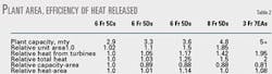
Experience has shown that plot size increases to the 0.81 power with train size, while the heat-output relationship to plant capacity fits a more linear trend. More-efficient plants are needed to reduce wasted heat that is released to the environment (Table 2). The examples shown in Table 2 are for typical configurations of Frame 5 Gas Turbines, Frame 7EA.
What is significant about this information is that, with plant size, the disposition of the waste heat becomes more important. The economics of the facility design will be driven not only by normal equipment and operating costs but also by optimization of design margin with the overall facility arrangement and capacity requirements.
Even with state-of-the-art equipment and thermally efficient designs such as combined-cycle power and process integration, the heat released from a large multitrain facility is significant and can affect the facility's ability to produce at relative design capacities for all potential ambient conditions.
Ensuring plant performance and lower costs requires prediction of not only how air coolers and fired turbines respond to changes in ambient conditions but also how they affect those ambient conditions near the facility.
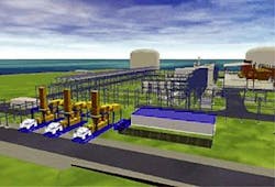
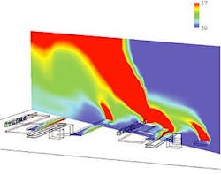
Computational fluid dynamics (CFD) provide a tool to meet that need. It is through the use of this tool that models can be built for extended facilities (future expansion) and for evaluation of how these will affect the area in general as well as each other (Fig. 9).
This modeling can and has been done on a large scale to look at the overall siting requirements, such as orientation and spacing, and then also on a detailed scale to look at the air velocity profiles around individual equipment.
This is useful when evaluating the impact of siting on process performance and developing design margins for equipment.
A typical siting study would include a preliminary model of the typical equipment geometry and air requirements along with any major obstructions to air flow (Fig. 10). Appropriate wind directions and speed are developed from local data to represent prevailing conditions.
Data are collected from model runs to evaluate the contribution of winds to plant performance. Different spacing or block rotation of facilities may be done to attempt to minimize the bulk influence of base conditions.
A more-detailed model can be constructed when more detailed information is needed for equipment design. It is necessary to ensure that air-cooled equipment and fired turbine drivers can operate at their predicted values, which in turn allow the plant to reach design capacity.
If the model shows that significant air recirculation is present, then this can either be accounted for in surface-area design margin, adjustment to the air inlet temperature, or other mitigation steps. It is important to recognize that the ambient conditions are in a constant state of flux, rarely staying in one state for more than a few hours.
This evaluation of equipment design is generally done on a weighted average to avoid excessive margins being applied for marginal ambient demands. A well-constructed CFD model lowers the total cost of the plant, while ensuring that the plant will operate as expected under a wide range of predicted ambient conditions.
"Green" designs
The Phillips-Bechtel LNG engineering team sees evidence of increasing client interest in reducing emissions in future LNG plants. There are many areas where careful attention to design can lessen the environmental impact of an LNG plant.
Following are some examples:
•The choices among industrial frame-type drivers, aero-derivatives, combined cycle, and between waste-heat recovery and simple fired heaters are driven by specific economics dictated by the owners and in the guidelines set forth during the early phases of a project.
For these costs to be borne by the planned project, the measurable potential benefits must compare favorably for the life of the project. With a portion of the plant feed being consumed for fuel (typically 5-11%), the contribution of efficiency and emissions technology to the overall plant economics is significant.
•Aero-derivative gas turbines have proven commercial experience in many applications and have attracted the attention of the LNG industry for many years. The issues of durability and life-cycle costs have been hurdles in the past, but time and effort by designers have reduced the resistance.
Typical thermal efficiencies over frame machines are increased by 30% and the CO2 emissions reduced by the same 30%. This occurs while the cost of power alone increases by only about 15%.
•Waste-heat recovery from turbine exhaust represents another potential fuel savings for the overall facility as well as emissions reduction. Special heating requirements, such as may be required for treating high acid-gas content in the feedstock or other energy-intensive units in the nearby facilities, can cause a significant increase in the fuel consumption.
These additional heat requirements can often tip the balance toward integrated heat recovery when evaluating life-cycle costs. Other heat-recovery technology exists for nonturbine exhaust streams as well and can be used effectively for low-grade heat requirements such as air preheat and absorption refrigeration.
•Combined-cycle cogeneration in conjunction with electric-motor-driven refrigeration compressors has the potential to reduce fuel consumption and CO2 emissions by as much as 40-50%. Although there is significant increase in equipment cost, initial internal evaluations show it could be attractive for large multitrain LNG complexes with total power requirements on the order of 500-800 Mw.
The large generators in the combined-cycle plant would provide the entire LNG plant's electric-power requirements, for refrigeration compressor drivers and the balance of the plant. This concept would be new for LNG plant operation and may offer other benefits in addition to reduced fuel and emissions.
Other potential benefits include increased reliability and reduced maintenance cost for refrigeration compressor drivers, economies of scale for LNG train sizes larger than 5 mty, and elimination of separate, smaller gas turbine-driven generators for the remaining plant electric-power requirements.
The high power density of the advanced technology combined-cycle systems enables a compact plant arrangement. Integrated gas turbine and steam turbine systems are capable of achieving up to 60% thermal efficiency, and their environmental impact per kilowatt-hour is the lowest of all gas-fired power generation and mechanical drive equipment.
Phillips and Bechtel have conducted several studies that indicate use of electric motor-driven refrigeration compressors and the combined-cycle approach is technically feasible and certainly should be considered when reduced emissions become more important.
To reduce the starting current requirements for these motors, a compressor-starting-torque converter can be used for coupling the electric motors to their associated compression train.
The authors

Amos A. Avidan is principal vice-president, Bechtel Fellow, and manager of petroleum and chemicals technology and development at Bechtel Corp., Houston. He manages Bechtel's technology centers of excellence, which include LNG and gas plants, refining, chemicals, and technology licensing. Before joining Bechtel, he was with Mobil Corp. for 20 years. Avidan holds a PhD in chemical engineering from City University of New York.

David B. Messersmith is LNG technology manager for the Bechtel Global Gas Group, Houston. He has served in various lead roles in the LNG projects for 9 of the last 11 years, including the Atlantic LNG project conceptual design through start-up and has 10 years' experience with MW Kellogg Co. and 11 years with Bechtel in various LNG and ethylene assignments. Messersmith graduated from Carnegie-Mellon University, Pittsburgh, with a BSc in chemical engineering and is a registered professional engineer in Texas. He is also a member of AICHE.

Robert Martinez is director of the Phillips-Bechtel LNG Global Alliance Product Development Center (PDC), Houston. He holds a BS in chemical engineering and a BS in chemistry from New Mexico State University and is a registered professional engineer in Texas.
Acknowledgments
The authors wish to thank Duke Energy Field Services' Joe Kuchinski, Jackie Strickland, and Roger Stone for their assistance in gathering and approving use of data from the Giddings plant and Dean Hudson, Aux Sable Liquid Products Inc. Thanks are also due Hans Kimmel of Ebara International and Vibhor Mehrotra of Bechtel.
References
- Avidan, Amos, Richardson, Frank, Anderson, Kent, and Woodard, Bill, "LNG plant scale-up could cut costs further," Petroleum Economist, Fundamentals of the Global LNG Industry, May 2001.
- Welch, S.K., "New gas for Europe - The Atlantic Mediterranean Basin," European Summer Gas Conference, London, June 23, 2000.
- Houston, Martin, and Redding, Phil, "The Atlantic LNG Project-A Case Study," SMI Energy Conference, London, Jan. 26, 1999.
- Ohishi, Masaaki, Nakamura, Moritaka, and Kikkawa, Yoshitsugi, "Availability of Refrigeration Process of Baseload LNG Plant," AIChE Spring Meeting, New Orleans, Mar. 10-14, 2002.
- Bauer, Heinz, "A Novel Concept," Hydrocarbon Engineering, May 2002, pp. 59-63.
- Johnson, L.L., Renaudin, Gerard, and Sguera, Oronzo, "Improvement of Natural Gas Liquefaction Processes By Using Liquid Turbines," 11th International Conference on Liquefied Natural Gas, Birmingham,UK, July 3-6, 1995.
- Kimmel, Hans E., "Optimized Rated Point Selection for LNG Expanders," AIChE Spring National Meeting, Second Topical Conference on Natural Gas Utilization, LNG-III - Technology & Equipment, New Orleans, Mar. 10-14, 2002.
- Peterson, Nelson B., Messersmith, Dave, Woodward, Bill, and Anderson, Kent, "Higher Efficiency and Lower Emissions for a Base-Load LNG Plant - Are You Ready for That?" Hydrocarbon Engineering, December 2001, pp. 26-28.