Procedure analyzes low-frequency ERW, flash-welded pipe for HCA integrity assessments
New US regulations, CFR Part 195 Section 195.452, require that special integrity assessments be made to address potential seam-defect problems in low-frequency, electric-resistance-welded (ERW) pipe where a failure of such materials could have affect a high-consequence area (HCA), specifically defined by the regulations based on risks to populated and environmentally sensitive areas. Pipeline operators must develop written integrity-management programs that embody in-line inspection or hydrostatic testing (or an equivalent technique) of segments of their systems that could affect an HCA.
Initial baseline assessments must be done on all affected segments by Mar. 31, 2008, and periodic reassessments will be required every 5 years thereafter. Specific responses to the findings of such assessments in terms of examinations and repairs are required.
Although the primary focus of the new regulations is to address effects of corrosion-caused metal loss and deformation anomalies (dents with and without metal loss, cracks, or stress risers), they also require the following with respect to ERW pipe (Para. 195.452(c)(i)):
"The methods an operator selects to assess low frequency welded pipe susceptible to longitudinal seam failure must be capable of assessing seam integrity and of detecting corrosion and deformation anomalies."
The spirit of this requirement appears to require action if, and only if, significant seam-related deficiencies are present or can be reasonably anticipated. This leaves open the option of categorizing these types of pipelines by performance so that potentially problematic pipeline segments can be subjected to special (i.e., seam-quality) inspections, while those that show little or no propensity for such problems can be subjected to metal loss and deformation inspections only.
This article is intended to establish a systematic procedure to permit an operator to characterize the relevant ERW pipe segments as to the likelihood of significant seam-related deficiencies.
ERW process
ERW line-pipe materials and a similar material called "electric-flash-welded" (EFW) pipe first appeared in the 1920s. Both processes involved making line pipe by cold forming previously hot-rolled plates or strips into round "cans" and joining the longitudinal edges of the cans by a combination of localized electrical-resistance heating and mechanical pressure.
The heat-softened edges were forced together, extruding excess material to the outside and inside of the newly formed pipe. This was immediately trimmed away, leaving smooth surfaces or at most a small protrusion along the bondline.
Both types of processes resulted in a narrow bondline and an associated local heat-affected zone HAZ). In many instances in the past and in all cases with modern ERW materials, the bondline-HAZ region was also subjected to a post-weld heat treatment. The purpose of this treatment is to eliminate zones of excessive hardness from the initial welding process because such zones could be susceptible to various forms of environmental cracking.
While EFW pipe is no longer made, ERW pipe is still manufactured but by improved methods and with improved materials. Currently made ERW materials represent high-quality line pipe and offer one of the best choices of materials for pipeline construction.
The need for this article arises because this was not necessarily the case 25 or more years ago. One must consider these older materials on a case-by-case basis because the quality of some lots of older ERW pipe is better than others. The quality, or lack thereof, is not a function of manufacturer. Both good and poor-quality lots have been made by most of the manufacturers in the 50-year period of interest (1930-80).
Before 1962, all ERW materials and EFW pipe were made by means of DC or low-frequency AC current (up to 360 cycles) using low-carbon steels made in open hearth or electric-arc furnaces and cast into ingots.
Problems with some older ERW pipe
The DC or low-frequency AC currents used for resistance heating required intimate contact between the rolling electrodes and the "skelp" (i.e., the plate or strip used to form the cans). Dirt, grease, scale, or other oxide films on the skelp could and often did cause enough interference to prevent adequate heating at the bondline interface. Momentary reductions or loss of current could and often did result in isolated or repeated areas of nonbonding called "cold welds."
Cold welds could be partly through the wall thickness or all of the way through. Even if a through-wall cold weld was formed, it might not result in a leak because typically such areas were completely filled with a scale that formed from the surfaces being exposed to oxygen while at a high temperature.
A significant number of cold welds in close proximity could so reduce the strength of the bondline that a rupture would occur when the pipe was subjected to pressurization. In these cases, a hydrostatic test to a sufficiently high pressure, if performed by the manufacturer at the pipe mill or the user before the pipeline is placed in service, would usually eliminate the most injurious areas.
An adequate test in this respect would be one carried out at 90% of the specified minimum yield strength (SMYS) for a pipeline to be operated at 72% SMYS. Before 1960, many sizes and grades of ERW pipe were tested by the manufacturer to levels of only about 75% SMYS, and before 1970, it was typical for liquid pipelines to be tested to no more than 1.1 times their maximum operating pressure (MOP).
Other phenomena that would result in poorly or weakly bonded ERW materials included electric-power fluctuations during welding, poorly trimmed skelp, cambered or twisted skelp, and inadequate or excessive mechanical pressure at the instant of bonding.
Running skelp too fast through an AC welder, for example, could cause the heat to fluctuate with the current cycle, resulting in a periodic variation in properties along the seam.
When broken along the bondline, these variations are made visible in terms of the fracture surface characteristics. The resulting pattern is referred to as "stitching."
A stitched weld does not necessarily create a pipeline-integrity problem because a defect of some kind other than the stitching itself must be present to start a fracture in a stitched bondline. A stitched bondline is generally characterized by low toughness, however, and only a relatively small defect may be required to start a fracture.
Poorly trimmed skelp may contain edge defects that end up on the bondline. Cambered or twisted skelp can result in offset edges at the bondline. The offset can be significant, reducing the net thickness by 30 to 40% in extreme cases.
Unfortunately, offset edges were seldom caught by visual inspection because the outside surface's trim tool removed the excess material from one side leaving the visible mismatch at the ID surface where it was hard to detect by visual inspection.
Improvements with HF ERW
Starting in 1962, manufacturers began to convert ERW mills from low-frequency-welding equipment to high-frequency (HF; 450,000 cycles) equipment. After 1978, it is believed that few if any low-frequency welders were still being used.
With the use of high-frequency current, the problem of contact resistance is virtually nonexistent. As a result, high-frequency-welded pipe tends to be relatively free of the bondline defects that were common in the low-frequency and DC-welded material.
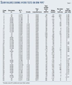
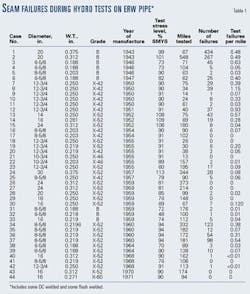
The performance of ERW materials has improved steadily with time. Table 1 illustrates that the number of test failures per mile decreased from levels as high as 6.5/mile in the 1940s to 0.01/mile in 1970 for pipelines tested to levels of 90% SMYS or more.
Not only has the ERW process itself improved, but cleaner, tougher steels have also been developed as the result of the conversion throughout the 1970s and 1980s to basic oxygen steel making, continuous casting, microalloying, and thermomechanical processing.
These trends have virtually eliminated three other potential problems associated with ERW seams: low-HAZ toughness, hook cracks, and grooving corrosion. These potential problems are not welding problems per se but have occurred in conjunction with ERW seams in the past.
It is safe to say that all low-frequency and DC-welded materials possess bondline regions that are prone to low toughness and brittle-fracture behavior. ("Low frequency" as used here refers to the range of 360 hz or less, typically used with "Yoder" mills before 1980. It is recognized that modern high-quality ERW pipe can be made with a variety of frequencies, though usually these are much higher than 360 hz, e.g., 150 to 450 khz.)
This tendency towards low toughness and brittle-fracture behavior exists because there was no way to prevent grain coarsening in the heat-affected zones. The enlarged grains invariably made the weld zones less tough and more prone to brittle fracture than the parent material.
To some extent, this tendency was reduced with the use of high-frequency welding because a smaller volume of material is heated than in the case of a low-frequency or DC process. In addition, by the 1970s most manufacturers were using microalloyed, thermomechanically treated skelp. These steps prevented or eliminated grain coarsening and thereby resulted in bondline regions of ERW pipe that are as tough as the parent metal.
The use of cleaner steels (i.e., with greatly reduced sulfur contents) has virtually eliminated the risks of hook cracks and grooving corrosion.
Hook cracks; grooving corrosion
The precursors for hook cracks are nonmetallic inclusions, primarily manganese sulfide "stringers." These flattened, nonmetallic inclusions are formed during hot rolling of plate or skelp. In general, they reduce the ductile toughness of the steel even in their normal position (i.e., layers interspersed between the rolling-elongated grain structure of the steel).
In this position, they can cause poor through-thickness properties that inherently reduce ductile-fracture tearing resistance but not necessarily the yield or tensile strength of the material. Near an ERW bondline, however, these weak layers become reoriented so that they are subjected to tensile hoop stress when the pipe is pressurized.
The layers may be of sufficient extent or so closely associated that the resulting planes of weakness separate, forming J-shaped (i.e., hook) cracks that curve from being parallel to the plate surfaces near mid-wall to being nearly parallel to the ERW bondline at the OD or ID surface.
These cracks, which can be up to 50% W.T. in depth and up to several inches in length, are in effect a pipe defect, not a weld defect, and their behavior is governed more by parent pipe toughness than bondline toughness. They tend to be much larger than bondline defects in the older materials because the low toughness of the bondline regions ensures that no large defects can exist after a hydrostatic test to a reasonably high pressure level.
Grooving corrosion is also a phenomenon that results from the sulfide-inclusion problem. The sulfide layers appear to make the material immediately adjacent to the bondline more susceptible to corrosion than the surrounding material.
As a result, when corrosion (external or internal) occurs in an area that includes the bondline, the corrosion rate will be higher in the bondline region than in the parent material. The frequent result of such corrosion is the creation of a long, sharp V-notch along and centered on the bondline.
In no case should such corrosion be treated or evaluated as one would treat or evaluate pitting corrosion in the parent pipe. The resulting anomaly is equivalent to a sharp crack in a relatively brittle material with a depth of penetration that is difficult if not impossible accurately to measure. It is worth noting that high-frequency-welded ERW pipe may be susceptible to hook cracks or grooving corrosion or both.
With the advent of the use of materials with even lower sulfur contents from the 1980s onward, however, one can expect that these problems will be less extensive than is likely in the case of the older low-frequency and DC-welded materials.
Assessment necessity
The first item on the agenda should be a thorough review of the segment at issue. The list of parameters to consider includes: diameter; W.T., grade; age; manufacturer; MOP; hydrostatic-test history; service ruptures or leaks; in-line-inspection history; coating type; cathodic-protection history; typical operating pressure cycles; type of product transported; and classification of seam type (low-frequency AC-welded ERW, DC-welded ERW, electric flash welded).
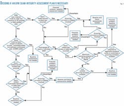
The roles these parameters play in the determination of the need for integrity assessment are discussed presently in roughly the order of their importance. Fig. 1 shows an example of a decision-making format for determining whether an ERW seam-integrity assessment plan is necessary.
Because it can be anticipated that an operator's plan for integrity assessments of ERW pipe will be audited by the US Office of Pipeline Safety (part of the Department of Transportation's Research and Special Programs Administration) or state regulators or both, the plan should include every ERW or flash-welded segment affecting an HCA. In many cases, it may be sufficient to note that the segment was considered but eliminated with no need for further analysis because:
- It consists of a newer, high-quality material having none of the potentially problematic characteristics that occasionally affect the older materials.
- The operating pressure level is so low that the risk of a seam rupture is negligible.
- The track record of the segment embodies no evidence of any seam-related problems.
Service-incident history
The first thing that should be considered when one is trying to decide whether a special seam-integrity assessment is needed for a segment of ERW pipe is the history of service leaks or ruptures that resulted from seam-related problems.
The incidents should be categorized as shown in Fig. 2. Causes of failure typically would be bondline defect; hook crack with no fatigue crack growth; hook crack with fatigue crack growth; offset skelp edges with no fatigue crack growth; offset skelp edges with fatigue crack growth; selective seam (grooving) corrosion; other (describe); and unknown.
If either a fatigue-related failure or a selective seam-corrosion (grooving corrosion) failure has occurred in the segment and that failure (or failures) occurred after the segment had been tested to a pressure level of at least 1.25 times the MOP, a seam-integrity-assessment plan should be developed.
The reassessment interval should be based on the crack growth rates or corrosion rates that can be inferred from past failures or from similar circumstances on other pipelines. If any of these types of failures have occurred, further analyses should be made of the times of previous tests in relation to the times of the previous failure to see whether the failures were time-dependent.
To be excluded from a seam-integrity-assessment plan, a segment must either have no recorded seam-related service failure or any seam-related service failure must be entirely explicable as a non-time-dependent event (e.g., the failure occurred because the pipeline was accidentally overpressured at or in excess of 1.25 times the MOP).
Service-pressure history
First and foremost, the MOP should be considered in terms of percent of SMYS:
- Is it relatively high (50 to 72% SMYS), intermediate (30 to 49% SMYS), or low (less than 30% SMYS)?
- What does the pressure spectrum look like over a 30-day period? A 1-year period?
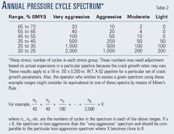
- Has the type of operation changed so that today's pressure cycles are more aggressive than before? Aggressiveness of pressure cycles can be crudely categorized for particular environments as shown in Table 2.
If fatigue failures have occurred or if the pressure spectrum falls into the aggressive or very aggressive category, a seam-integrity assessment plan should be developed. The reassessment interval should be based on crack growth rates that can be inferred from past failures or from similar circumstances on other pipelines.
To be excluded from a seam-integrity assessment plan, a segment must have exhibited no failure involving fatigue crack growth and its pressure cycle aggressiveness must be shown by analysis to be incapable of causing the margin of safety demonstrated by its last hydrostatic test to be eroded within twice the expected life of the pipeline.
Test-pressure history
The test-pressure history of each segment should be reviewed and the information shown in Fig. 3 should be compiled.
If the test was conducted after the pipeline had been in service, special note should be taken of any seam failures (leaks or ruptures) that occurred well below 1.25 times the MOP or below the level of a previous test. These may be the result of fatigue-enlarged defects or selective seam corrosion.
The causes of all test breaks or leaks should be determined in any new test and studied, if known, in the case of prior tests. The expected causes will be the same as those discussed previously under service-incident history. Failures that occur at the highest pressure that the pipe has ever experienced are often associated with manufacturing defects.
Large numbers of failures often lead to "pressure reversals" in which defects fail at lower levels than they were subjected to during a previous pressurization. If enough pressure reversals occur, the likelihood of a reversal of a given size can be predicted.
If the investigations of test failures indicate the presence of time-dependent defect growth (i.e., fatigue or selective seam corrosion), a seam-integrity-assessment plan should be developed. The reassessment interval should be based on crack growth rates or corrosion rates that can be inferred from past failures or from similar circumstances on other pipelines.
If hook cracks or offset skelp edges are revealed by test breaks but no evidence of fatigue is found, the nature of pressure cycles on the system should be reviewed to see if fatigue could become a problem. To be excluded from a seam-integrity-assessment plan, a segment should exhibit no test breaks when tested to a pressure level of 1.25 times MOP. Other scenarios that may warrant exclusion could be those in which test breaks occurred but only at test pressure levels well in excess of 1.25 times the MOP and in which large pressure reversals are extremely unlikely.
Pipeline age
As Table 1 shows, the performance of ERW pipe materials improved steadily between 1940 and 1970. This trend appears to have been a consequence of technological improvements in the manufacturing process.
While the age of a pipeline segment alone cannot be used to determine whether it should be subjected to a seam-integrity inspection, the pipeline operator should consider whether a combination of age-related factors and other factors points to the need for a seam-integrity assessment. For example, a 1940s-vintage pipeline may warrant such an assessment if it is subjected to aggressive pressure cycles or if it is found to be significantly affected by corrosion-caused metal loss.
Corrosion
If either external or internal corrosion is found on an ERW segment, the potential exists for selective-seam corrosion. This will occur if an area of metal loss overlays the bondline region and if the bondline region is susceptible.
One can expect that an ERW seam made before about 1980 will be at least somewhat susceptible to selective-seam corrosion, although such susceptibility varies widely from one material to another.
A pipeline with a known selective-seam-corrosion problem is clearly a candidate for a seam-integrity assessment. A bare pipeline, a pipeline with poor coating, or an extensively disbonded coating could be a candidate, although it may be possible to establish with electrical-survey measurements and excavations whether external selective-seam corrosion is likely.
To be able to exclude a segment from a seam-integrity assessment plan, the operator should have a high degree of confidence that no selective-seam corrosion is occurring. Transporting only noncorrosive products ensures that no internal corrosion can affect the seams.
The absence of internal corrosion can be verified by a metal-loss inspection without the need for a seam-specific assessment.
Even if some internal corrosion is occurring, the operator may be able to ascertain that all seams are in non-affected orientations.
From the standpoint of external corrosion, it is possible that the responses required by metal-loss inspection will be adequate to demonstrate with good certainty that no selective-seam corrosion is occurring.
Also, pipelines laid with the seams in the top quadrant of the pipe may be less susceptible to external selective seam corrosion than those where no preference was given to the clock position of the seams.
Categories
It appears possible to separate ERW pipe segments into three categories based on attributes of the segments and the findings of integrity assessments for metal loss. The categories are:
1. Clear-cut evidence shows that time-dependent deterioration of seam anomalies is occurring. Segments in this category will require a special seam-integrity assessment plan.
2. Despite no direct evidence of ERW seam deterioration, conditions of operation and attributes of the segment suggest that seam deterioration is likely. For pipeline segments in this category, studies of the attributes, the operations, and the results of other integrity assessments should be made to determine whether a special seam-integrity assessment plan is necessary.
3. Attributes of the segment, the operating conditions, the history of the segment, and all evidence generated by other integrity assessments make reasonably clear that no time-dependent seam deterioration is occurring. No special seam-integrity assessment plan is needed for segments in this category.
The various types of data outlined in this article should be gathered and assessed to establish the appropriate category for each ERW pipeline segment. Detailed analyses as suggested here can be used to determine whether those segments that fall into the second category will require a special seam-integrity-assessment plan.
Acknowledgment
The author is particularly grateful to Rich Turley of Marathon Ashland Pipe Line LLC for helping to formulate the essential steps in deciding when an integrity assessment is needed and for making significant input to Fig. 1.
Based on a presentation to ETCE 2002: ASME Engineering Technology Conference on Energy, Feb. 4-6, 2002, Houston.
The author
John Kiefner is president of Kiefner & Associates Inc., Worthington, Ohio, which he founded in 1990. Over the past 33 years, he has specialized in conducting research on pipeline material behavior and pipeline defects and repair methods. He has developed a criterion for assessing the strength of corroded line pipe and guidelines for hot tapping or repairing pipelines in service. He also conducted research programs on the use of hydrostatic testing and in-line inspection to evaluate the integrity of existing pipelines. Kiefner received his BS and MS degrees in civil engineering from Purdue University, Lafayette, Ind., and PhD from the University of Illinois. He is a registered professional engineer in Ohio and a member of ASME and NACE.


