Expandable tubulars gaining industry confidence
In a play on words, Bill Dean, business development manager for Houston-based Enventure Global Technology LLC said expanding solid tubulars was a "pipe dream" of which many in the industry were skeptical 3-5 years ago when work began on the idea.
Speaking to a December conference of the International Association of Drilling Contractors (IADC) and Offshore Operators Committee (OOC) in Houston, Dean said that the company has now expanded almost 8 miles of tubulars in 50 installations.
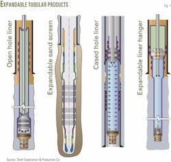
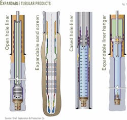
In 3 years that Enventure has been working on solid expandable tubulars, the company has developed four different products, including openhole liners, expandable sand screens, cased-hole liners, and expandable liner hangers (Fig. 1).
Deployment of expandable sand screens through reformable multilateral junctions also highlights the industry's progress in pushing expandable technology forward.
Development
Solid tubular expandable technology, developed to allow wells to be drilled with fewer casing strings, employs normal weight casing with 80,000-psi yield strength. Operators have the option of using 41/4-in. liner systems with 55,000-psi yield strength material, which is more cost effective for low-pressure casing patch jobs.
Adapting automotive technology, engineers have slightly modified the metallurgy of normal oil country tubulars to give it the physical characteristics needed for cold working the steel which results in plastic deformation.
The electro-resistive welded pipe starts out as flat roll that ensures a constant and uniform wall thickness throughout.
Dean pointed out, showing a demonstration video of a solid liner expansion at surface, that the pipe temperature increased only 40° F. above ambient from the expansion process. This process is not hostile to the material, and cold working of the liner does not change its metallurgy, he explained.
The pipe is taken above the elastic limit and plastically deformed with a solid tapered cone as the cone is pumped through the liner with cement pumps or the rig pumps. Engineers design the liner's final dimensions by changing the OD of the expansion cone, which determines the expanded liner's ID.
Openhole liners
The use of openhole expandable liners involves underreaming the wellbore below the last casing string. Depending on lithology and experience drilling formations in the area, operators may use bi-center bits or conventional bits with near-bit reamers to drill the required oversized hole.
Dean explained that with an operator installing 75/8-in. expandable liner in a well with 95/8-in. base casing, the OD of the liner will expand to 8.5 in. or slightly larger. If the operator had drilled the hole below the 95/8-in. liner with a standard 8.5-in. bit, the wellbore would be too small.
Crews expand the liners into the oversized open hole, upward, and into the overlap with the base casing string, creating an elastomer seal in the overlap interval (Fig. 1).
Dean said the expansion process normally proceeds at about 20 fpm and is driven by pumping mud down the drill pipe. In the case of 133/8-in. liner, it takes about 1,800 psi. All of the systems are designed to expand with less than 5,000 psi, making the technology applicable to existing rig equipment, he added.
Run procedure
During installation of an expandable liner, crews run the expansion cone launcher system first, followed by the remainder of liner, including the overlap section with the external elastomer seals (Fig. 1).
With the liner hanging from its top in the rig floor slips, the crew picks up the drill pipe, runs it through the liner, and screws it into the cone. After make up of the drill pipe to the cone at the liner's bottom, the rig lifts up to remove the false floor and slips and runs to TD in the conventional manner.
As the crew runs the liner with the drill pipe attached to the liner bottom, the drill pipe pulls the liner in back behind it, rather than pushing the liner in the hole.
Dean said that not many problems have occurred in getting expandable liners to bottom, considering that they have externally flush joints, the wellbores are enlarged due to under reaming required below the last casing string, and drill pipe is connected to the liner bottom effectively pulling it into place.
This procedure differs from the conventional method of pushing liners into the well, with the drill pipe connected to conventional slip-type liner hangers at the liner's top.
Once the expandable liner is on bottom, the rig can circulate down the drill pipe and up around the outside of the liner.
The operator has the option of pumping the cementing operations either before or after liner expansion. Dean said, "In fact the last several jobs had to be done with the cementing performed after the expansion."
Expansion process
To initiate the liner expansion process, a latch down plug is pumped down the drill pipe, which seats into the bottom of the expansion cone's launcher system creating a pressure chamber below the expansion plug.
As crews continue pumping mud down the drill pipe increasing pressure in the chamber, the pressure acting on the expansion cone cross sectional area drives the cone up into the liner.
The driller maintains the string weight. The drill pipe rises on the rig floor as mud is pumped and the liner expands.
The process of expanding the tubular material must obey material conservation laws, meaning the expansion process can neither create nor destroy the tubing material, Dean explained.
In the case of the openhole solid expandable liner, the expansion cone moves upward during expansion, causing the pipe to shorten and lose wall thickness as material is consumed with the increased pipe diameter.
Dean said the pipe experiences 4-5% reduction in length and 3-4% reduction in wall thickness. If the installation called for 1,000 ft of liner, the operator would run an extra 50 ft of expandable pipe, up in the overlap, to account for shrinkage effects.
The same is true for wall thickness, meaning that calculations to determine burst and collapse pressure rating of the expanded liner must consider the 3-4% wall thickness reduction and post-expansion dimensions.
Dean said the expansion process is very forgiving, allowing the rig crew to start and stop expanding the liner as operational considerations dictate.
If any debris buildup above the expansion cone is expected, the rig can lower the drill pipe disengaging the expansion cone from the liner, after stopping the expansion process, and circulate mud past the expansion cone to remove the debris.
The rig can stand drill pipe back in the derrick, which is the fastest way, or laying down singles as it proceeds with the liner expansion process.
Liner lap
The liner lap, or elastomer-coated "anchor hanger," creates a seal as the liner expands to the ID of the casing above the openhole liner.
The elastomer seals on the outside of the liner compress, forming a robust seal. Engineers choose the elastomer materials, which can be nitrile, Viton, or Aflas rubber, depending on the expected bottom hole temperature and chemical exposure.
Dean said, "Just to give you an idea how robust this seal is, one 12-in. seal will support 500,000 lb of mechanical hook load, at 8,000-psi burst or 5,000-psi collapse pressure."
Since the liners are intended for drilling operations, engineers have performed torque tests on the system. With a total of five seals for redundancy, the anchor hanger system provides a very robust seal, Dean added.
When the expansion cone exits the top of the liner, the rig can circulate out excess cement, pressure test, pick up the next drilling assembly, drill out, and continue drilling for the next liner.
Dean said rigs could run the expandable liners at the same speed as conventional liners; the expansion process for 1,000-ft liner should take roughly 3-3.5 hr total expansion time.
Deepwater applications
Dean discussed several case histories in the Gulf of Mexico highlighting expandable liners as an enabling technology for deep water. Most of the expandable liner installations have been in the gulf, he said.
Expandable liners allow operators to drill to objective reservoirs with sufficient hole-size remaining to perform completion work.
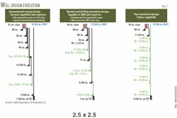
Expandable liners also reduced wellbore size, allowing a smaller riser and BOP stack at the drill ship (Fig. 2).
The maximum liner expansion ratio or percent change in ID is 25%, said Dean, but typical expansion ratios range 10-15%.
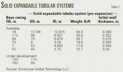
For 12% expansion of 133/8-in. casing, an expandable liner regains 1.5 in. of inside diameter. This means that for the larger two sizes (133/8 in. and 95/8 in.), operators can rerun that same liner size through itself (Table 1).
The expandable 133/8 in. liner now provides for two casing points in the well plan with the same liner size (Fig. 2).
Dean said, "The industry is advancing into deeper water in the Gulf of Mexico and in order to maintain that advance, we need to reduce well costs."
He added that by using expandable liners and still being able to get 7-in. casing to TD, operators can look at using reduced riser sizes and mud line packages, allowing them to use smaller, third-generation drill ships, significantly lowering well cost.
Dean said that Shell has documented, from savings in the gulf during the last couple of jobs, that each expandable liner has saved the company roughly $5 million.
Nested liners using large expandable liners promise a true monobore well design because the same casing size can run inside of itself (Fig. 2).
Paul Goodfellow, drilling and completions operations manager for Shell International Exploration and Production Inc., said the company is working to extend and test the technology in 2002, with the objective to take it offshore to the gulf in 2003.
Nested liners
An Oklahoma City-based operator ran two expandable liners in a horizontal well to control lost-circulation problems, according to Dean.
In smaller liner sizes, the expansion ratio allows one liner to fit tightly inside the previously expanded liner. Not only can operators expand just one liner independently, but also they can drill ahead and install another expandable liner, using the ID of the previously expanded liner to seal against.
This is important because it allows operators to minimize reduction in well diameter or tapering, with subsequent casing strings.
In the horizontal well, the operator ran a 61/8-in. liner inside the 75/8-in. base casing and expanded it, which resulted in 6-in. ID. After drilling ahead, the company ran a 51/2-in. liner and expanded it to seal inside the 6-in. liner run previously, which resulted in a 51/2-in. ID.
This gave the company enough remaining hole diameter to drill to TD and perform the required completion.
Success rate
As expected with new technology, not every job has been a success. Dean reported that four jobs were unsuccessful for various reasons.
A connector failure occurred during an early job with 75/8-in. liner, after expanding 1,200 ft of the planned 2,200 ft. Examination of the connectors revealed that they had experienced over-torque.
Engineers subsequently redesigned the connectors and adjusted the torque requirement for make-up. No connector failures have occurred since, said Dean, with 10,000 ft deployed and 250 connectors of 75/8-in. size now expanded.
In a South Texas well, Shell experienced rupture of a 6-in. expandable liner that was related to differential sticking. Four Vicksburg sands, which were being cased behind the 6-in. liner, exhibited differential pressures ranging from 2,500 to 6,000 psi.
As mentioned previously, the liner length must shrink during the expansion process, as required by material conservation. Once run into the well, the pre-expanded liner became differentially stuck due to pressure differences within the sands, preventing the liner from moving laterally during expansion.
With lateral movement of the liner impossible, excess wall thinning occurred, resulting in a 2.5-in. tear or rip in the middle of a joint. Shell had diagnosed the problem and identified the tear by ultrasonic casing inspection.
Dean said, "Differential sticking does present a challenge. We've done a lot of testing and modeling. Up to about 3,000 psi of differential pressure we feel comfortable, but over that, we have to look at the design."
Plotting the results year-by-year, the success rate has increased to 85-87% of the jobs in 2001.
The deepest installation is a little more than 22,000 ft and the highest temperature so far is 295° F. Dean said he hoped that in January that will fall. "We're on schedule to do an installation at 380° F."
Installed in November, an Oklahoma well holds the record length for solid expandable tubulars of 3,150 ft of 75/8-in. liner, said Dean.
Cased hole liners
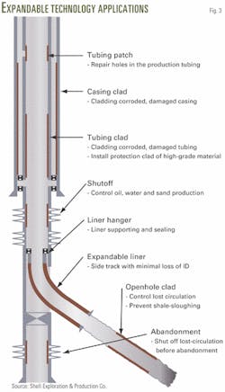
Expandable tubulars serve effectively as a casing repair solution or internal cladding to seal off intervals that may have experienced corrosion or to seal off old perforations that are no longer needed for production.
An operator may want to seal off existing perforations in order to perforate a lower zone and perform some kind of stimulation, not possible with the upper perforations open.
Dean said that more than 20 installations of cased-hole liners have been completed. Enventure is looking at developing corrosion-resistant materials for these applications, he added.
Fig. 3 illustrates various methods and uses of solid expandable tubulars for internal cladding.
Liner hangers
Enventure developed an expandable liner hanger system in a single size (75/8-in., 8.310-in. OD) for applications for which non-expandable liners or screens must be hung below 95/8-in. base casing (OGJ, Aug. 6, 2001, p. 41).
The expandable liner hanger, with five 12-in. long elastomer seals, is rated for holding an axial load of 425,000 lb and has a 7.0-in. ID post-expanded drift. Shell Exploration and Production Co. and BP PLC, Houston, have trial tested the system in two wells.
Simon Harrall, solid expandable systems manager for Houston-based Weatherford International Inc., said the company is currently developing a solid expandable liner system, primarily for use as liner hangers with its line of expandable sand screens.
The company currently hangs the sand screens from conventional liner hangers that use slips.
Alternate bore liner
Weatherford developed the slotted expandable alternate bore liner (ABL) system to resolve lost-circulation problems. The ABL system uses a 2-in. thick reinforced cement sheath, resulting from a balanced cement plug, to stop lost circulation.
With the ABL system available since 1997, Harrall said that most of the jobs have been done within the last 2 years. He believes the industry's acceptance of expandable tubular technology has grown.
Weatherford says it has performed 20 ABL deployments for a total length of 6,500 ft run, with nine jobs done in 2001.
Petroleum Development Oman LLC (PDO), Muscat, is now starting to design well programs with use of the ABL as part of the well program, said Harrall. Previously, it was only used to solve lost-circulation problems that came up unexpectedly. (OGJ, Sept. 3, 2001, p. 56).
Expandable junctions
Graham McKay, Mark Roonan, and Ian Brown said, in a company publication, that BP PLC has installed the world's first multilateral well with a Level 6 reformable sealed junction and expandable sand screens 320 km northeast of Aberdeen in the North Sea.1
Harding field Well No. PS2yx, completed in the extremely permeable but unconsolidated Balder formation, presented considerable design challenge to maximize production from two horizontal laterals, while maintaining downhole sand control.
The well employs Baker Hughes Inc. TAMIL (Technology for Advancement of Multi-Laterals) Level 6 formation junction, which uses expandable or reformable technology to provide complete mechanical seal, without relying on either matrix consolidation or cement to eliminate sand production.
Once the junction laterals were expanded or reformed, crews drilled and completed the two 6-in. lateral legs to provide the combined production interval of 2,600 ft.
BP ran Weatherford's expandable sand screens, landed in the Level 6 junction laterals, which after expansion yielded a screen inside diameter of 5 in. across the producing interval.
The authors said "The value of increasing reserves and accelerating production through adoption of new technology will contribute significantly to Harding delivering lower lifting costs and help to attain an ultimate field recovery factor greater than 65%."
Expandable screens
Harrall said Weatherford supplies expandable sand screens, under a Shell patent. Currently, the company has run a cumulative 58,500 ft of expandable screens, mainly in the 4 and 51/2-in. sizes, with the longest deployment of 7,030 ft of 4-in. screen, in a North Sea horizontal gas producer.
And operators land the expandable screens on conventional liner hangers set on slips. After setting the hanger, crews expand the sand screens from the top down, using a compliant rotary expansion tool.
The tool is compliant in that the pistons extend or retract if increased or decreased hole diameter is encountered, where expansion force is created by means of a tapered roller cone and compliant rotating balls mounted on traveling pistons.
Reference
- McKay, G., Roonan, M., and Brown, I., "Harding PS2yx - Another BP World First; a Multilateral Well with a level 6 Re-formable Sealed Junction Completed with Expandable Sand Screens," Wellconnected, Dec. 2001, BP PLC, Upstream Technology Group, Vol. 3, Issue 12, No. 29.
