Modern design, troubleshooting tools create a successful FCC revamp
Based on OMV AG's need for increased conversion and selectivity for propylene production, UOP LLC revamped its existing stacked FCC unit to include Optimix feed distributors, vortex separation system (VSS) riser disengaging, and a modern reactor stripper design.
New reactor internals increased the feed rate, but the design retained the existing reactor shell to maintain a constant structure and foundation load. Internal clearances were closer than a typical new reactor system. The existing stripper also received new internals.
Postrevamp operation exceeded the expectations for propylene yield. Catalyst containment in the reactor, however, was not as good as expected. OMV and UOP developed a joint risk-management plan to address this problem.
We identified the root cause of catalyst losses using gamma scans, tracer scans, X-ray imaging, and physical testing of the catalyst in the main column bottoms. In addition, UOP's engineering group reviewed design parameters and as-built equipment, and used computational fluid dynamic (CFD) simulations.
The companies developed a risk-cost comparison to arrive at the final solution after completing the root-cause analysis. UOP engineered the resulting design modifications, which eliminated catalyst losses from the unit while preserving yield performance.
Background
The OMV FCC unit, located in the Schwechat, Austria, refinery, started up in 1963. It is a classic UOP stacked-FCC unit originally designed for 10,250 b/d of fresh feed (with a combined feed ratio of 1.7). It was revamped several times to increase capacity and to incorporate various technology improvements.
In 1998, OMV decided to revamp the unit to increase conversion, double propylene yield, and slightly increase capacity. A nearby petrochemical facility increases propylene value vs. other FCC products.
The revamp design basis was set at 26,815 b/d with a minimum propylene yield target of 8.2 wt % of feed. The design incorporated Optimix feed distributors, a VSS riser disengager, and new reactor stripper internals to achieve this target.
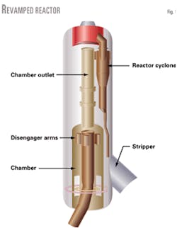
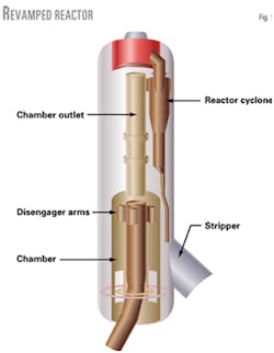
Fig. 1 shows the reactor revamp configuration. A new gas plant accommodated additional LPG product. After the revamp the unit started up in August, 2000.
Postrevamp performance
The unit achieved feed rate and propylene yield targets when it was restarted after an adjustment time to set the unit to new operating conditions and catalyst properties (including ZSM-5 additive).
Catalyst containment in the reactor, however, did not achieve its target due to catalyst in the main column bottoms product. We did not, therefore, consider this a successful revamp even though the unit achieved process performance goals.
Losses were not high enough to force an immediate shutdown but did warrant an investigation to identify the root cause and find a solution. Target losses from the reactor were less than 0.5 ton/day; actual initial loss rate varied between 3-5 ton/day at lower-than-design unit throughputs.
OMV minimized reactor steam rates and increased unit feed rate to almost design values, which lowered catalyst losses to less than 3 ton/day and improved unit profitability.
Risk management plan
UOP FCC specialists and OMV refinery personnel formed a multidisciplinary team to address the catalyst loss problem. The team's goals were to:
- Identify all possible problem causes.
- Establish a way to operate safely with higher catalyst losses and an increased risk of erosion.
- Develop a long-term solution.
The plan included several activities for efficient completion. Operational and inspection activities included:
- Monitoring main column bottoms exchangers for temperature changes that would indicate catalyst fouling.
- Reviewing piping configurations for high-velocity areas that would need extra on-line inspections.
- Controlling the main column bottoms flows to minimize velocities.
- Regularly inspecting the main column bottoms pumps.
Engineering design activities resulted in additional specifications to increase the wear resistance of pumps and control valves, and specifications for a filtration-settling system in case the solution was not 100% effective.
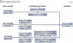
The investigation team applied "six sigma" methodologies to list all possible causes, identify contributing factors to catalyst losses, and gather data to support or eliminate each possible cause. The team also conducted on site FCC operational testing to confirm technical observations and conclusions.
Fig. 2 shows a typical logic diagram used for this analysis. The problem was unusual because the VSS design did not have this problem in 18 prior revamps.
Engineering evaluation
The engineering team reviewed the project design parameters and components (design and actual operating conditions) for any errors or deviations from established design and revamp criteria. Parameters included velocities, fluxes, and geometric relationships. Some deviation or compromise from normal design criteria may have occurred due to new reactor internals in an existing reactor vessel.
The engineering team benchmarked other successfully operating VSS reactor designs to identify any parameters that were beyond UOP's range of operating experience. They discovered no deviations from established guidelines.
Detailed cyclone design
UOP contacted the cyclone vendor for a detailed validation of the cyclone design for this reactor revamp project, including a construction drawing review. Parameters included inlet and outlet velocities, ratios of inlet duct dimensions, and length-diameter ratios.
UOP checked the cyclone parameters against design and actual operating conditions. The design efficiency was adequate for the given process conditions. The flapper valve was slightly modified from the original project specification but was in good working condition and was calibrated for the desired test weight.
On site operational testing
Operations monitoring, testing, and documentation of catalyst losses from the reactor began shortly after the FCC unit started up. The catalyst loss rate increased at higher feed and catalyst circulation rates.
The loss rate was less sensitive to changes in cyclone velocity and pressure drop.
External-source gamma scanning assisted our efforts to discover the cause of catalyst losses. The gamma ray source scanned the diplegs to detect the presence of catalyst. We compared this scan to a blank calibration performed before operations.
Gamma scanning indicated that the northwest reactor cyclone dipleg appeared to contain no catalyst. An empty dipleg represents an abnormal condition and is probably associated with high catalyst losses. None of the diplegs showed a high catalyst level, which would indicate a plugged dipleg or stuck closed flapper valve.
We used two additional testing techniques to investigate the apparent problem further in the northwest dipleg: tracer injections and X-ray inspections. Catalyst-phase and vapor-phase tracer injections tested for normal and abnormal flow paths of vapor and catalyst through the reactor.
Long exposure X-ray film of the reactor dipleg counter-weighted flapper valves would determine if one of the flapper valves was stuck and not responding correctly to changes in dipleg catalyst flux.
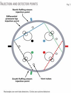
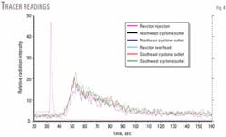
Radioactive gas injected into the reactor annulus indicates preferential flow or higher velocity to any one cyclone. Figs. 3 and 4 show the injection point and tracer results at the cyclone outlets.
There was no apparent backflow up the diplegs and gas distribution in the reactor was reasonably even.
Radioactive catalyst injected into the riser followed the path of solids through the system.
A limitation of tracer testing is that it is not a weight-balanced test. Flow indications are based on the energy detected and are relative to the tracer concentration and distance from the detectors.
Effective analysis depends on correct data interpretation and assumptions. In this case, we wanted to determine if there was preferential flow of solids to any cyclone that would overload that cyclone.
Test results showed that catalyst distribution to each of the four cyclones was 25% (±3%); solid maldistribution to the cyclones was not the problem.
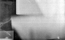
Long exposure X-ray film examined the operating cyclone dipleg flapper valves. This test shows if a valve is fixed open or closed and that the valve is moving if the flapper edges are blurred.
Fig. 5 shows the northwest flapper valve that may not have been operating, as indicated by the gamma scan test. We X-rayed all four flapper valves and tabulated the results.
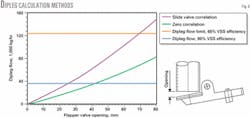
Fig. 6 shows the methods used to calculate flow in each dipleg for observed valve openings (maximum and minimum). The diplegs were operating well below maximum flux and VSS separation efficiency was above its design value.
Based upon maximum achievable flapper valve and dipleg flow, the system can still operate properly even if VSS separation efficiency is as low as 65%.
With a low actual dipleg catalyst flux, however, potential dipleg defluidiziation, which can contribute to cyclone bypassing, is a concern.
CFD modeling
Computer modeling of complex multiphase flowing systems (vapor and solid, in this case) is a powerful tool used to design and troubleshoot fluidized systems such as the FCC process.
UOP conducted a CFD modeling effort to investigate and identify the cause of catalyst losses from the reactor. The CFD model predicted hydrodynamic characteristics and catalyst separation performance for the riser, VSS primary separation device, VSS outlet duct, and cyclone inlet.
The 3-D model required for modeling the catalyst separation system is complex and computationally intense. Individual model runs can require as much as 1-2 days of computer time to converge on a solution. CFD modeling work is generally built up sequentially by:
- Developing the baseline system using actual operating conditions.
- Using the model to compare similar designs.
- Using the model to test the effectiveness of physical modifications to the catalyst separation system.
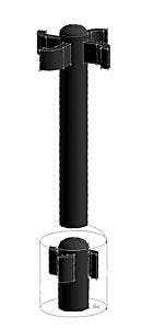
Fig. 7 shows the CFD model consisting of the VSS chamber and disengaging arms, connecting duct, and cyclone inlets. We developed the model to determine the effects of maldistribution and to identify gas and catalyst flow patterns throughout the system.
The as-built cyclones included a conical internal gas tube rather than a typical cylindrical gas tube. Although this type of geometry is successful in other units, the gas tube's top was closer to the gas inlet stream (34 mm) than the tube's bottom.
Reactor physical constraints also caused the cyclone inlet geometry to differ slightly from other VSS designs.
CFD modeling results showed cyclone flow patterns that may have caused catalyst to bypass the cyclone. Catalyst losses relative to the circulating catalyst were small; the model may not have been sensitive enough to exactly calculate such small quantities.
A normal catalyst circulation rate to cyclones is about 320,000 lb/hr, and the collection efficiency is about 99.99%.
Actual cyclone efficiency for the 3-ton/day loss was 99.91%, a small difference that is difficult to model accurately. The model did show, however, that flow patterns could exist to cause such a catalyst loss.
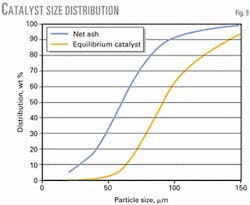
Fig. 8 shows velocity flow vectors at the cyclone inlet; possible flow of catalyst directly towards the cyclone gas tube may contribute to catalyst losses. Fig. 9 shows that the particle size distribution of recovered catalyst was consistent with a cyclone efficiency problem.
The sample was taken after the problem had been ongoing and the equilibrium catalyst (e-cat) average particle size (APS) reflects a loss of fines. Even though the e-cat APS increased to a maximum of 105 mm, straight standpipes and slide valve control precluded any catalyst circulation problems.
Recommendations
Our investigations and evaluations eliminated several possible causes and associated contributing factors. Cyclone bypassing was the root cause of catalyst losses.
We developed several possible solutions to address the contributors to cyclone bypassing. A risk-cost comparison provided a final solution.
The analysis included new equipment lead time, equipment cost, mechanical work duration, degree of complexity, and an estimate of the probability of success. Team recommendations included:
- Reducing the dipleg to 8 in. and installing new flapper valves, including new quality control requirements for shop testing.
- Replacing the cyclone gas tube with a cylindrical tube.
- Modifying the cyclone inlet duct to eliminate potential flow to the cyclone gas tube.
The combined effect of these modifications was more clearance between the cyclone inlet stream and gas outlet tube. The cyclone inlet duct probably caused the inlet bypassing, but the data did not clearly identify a single root cause.
OMV implemented all the modifications to maximize the probability of success. UOP worked with OMV to optimize construction planning and sequencing.
For easier future maintenance and to shorten the turnaround time, OMV installed new cyclones rather than modifying the existing ones in situ.
Implementation
The unit shut down in August 2001, at which time a careful inspection of the reactor internals verified the conclusions from using the diagnostic tools.
OMV drained and weighed the catalyst from each cyclone dipleg. The variation was less than 2 lb, which confirmed proper dipleg operation.
Flapper valves were in good condition and moved freely.
Cyclone inlets showed some signs of catalyst flow and the cyclone gas outlet tube had some erosion on the bottom edge.
The evidence proved that the cyclone inlet configuration and proximity of the gas outlet tube were likely the main contribuors that caused catalyst losses. The unit restarted after the reactor received the recommended modifications.
Catalyst losses from the reactor fell to less than 0.1 ton/day, well below the original design estimate. The yield pattern remained unchanged. The test run feed rate was 27,700 b/d with a propy lene yield of 8.5 wt % of feed, both above design values.
Operational monitoring and equipment inspections returned to normal levels.
The authors
Lawrence A. Lacijan is senior manager for FCC technical services at UOP LLC, Des Plaines, Ill. He has also worked in catalytic reforming, hydrocracking, hydrotreating, and sulfur recovery process technology. Lacijan holds a BS in chemical engineering from the Polytechnic University of New York and is a registered professional engineer in Illinois.
Steven Niewiedzial is the technical manager of the mechanical technology group at UOP, Des Plaines, Ill. He has also served as a FCC mechanical specialist at UOP prior to transferring to his current position. Niewiedzial holds a BS (1990) in mechanical engineering from the University of Illinois, Champaign-Urbana.
Based on a presentation to the NPRA Annual Meeting, Mar. 17-19, 2002, San Antonio.
