Contracting strategy eases early conclusion to Kuito expansion
Cabinda Gulf Oil Co.'s (CABGOC) contracting strategy was an important factor in the on time installation of Kuito Phase 1C subsea production facilities in deepwater Block 14, off Angola's Cabinda province.
For installing this third part of Phase 1 development, ABB Offshore Systems Inc. and Coflexip Stena Offshore Group (CSO) used key project team members, previously involved in Phases 1A and 1B, to optimize project management and execution. Lessons learned from 1A and 1B further enhanced the project progress.
Their planning, contracting, and management of the fabricated packages in Lobito, Angola, resulted in successful completion of these items on time and with high quality, even though the 1C project had a short 101/2 months duration from contract award to system acceptance.
CABGOC awarded the Kuito 1C project at the end of September 2000. System acceptance was achieved on Aug. 18, 2001.
System acceptance required three tree systems, manifold, flowlines, and a gas lift system to be manufactured, installed, and commissioned.
Kuito development
Kuito field is at an average 400-m water depth in Block 14, which covers 1.5 million acres in 200-1,500-m water depths.
As operator of Block 14, ChevronTexaco Corp. unit CABGOC has announced six other discoveries in the same block. Block ownership includes CABGOC, 31%, Agip Angola Exploration BV, 20%, TotalFinaElf E&P Angola, 20%, Sonangol, 20%, and Petrogal Exploracao, 9%.
Kuito field, discovered in May 1997, produced first oil in December 1999 from Phase 1A.
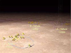
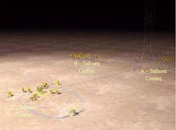
Field development will have multiple phases, with the first phase divided into three parts: 1A, 1B, and 1C (Fig. 1).
Phase 1A
The Phase 1A subsea production center consists of 12 wells around a 12-slot production manifold. Two 11-in. production flowlines and a 6-in. test line link the manifold to a floating production, storage, and offloading vessel (FPSO).
An umbilical system having two gas lift-methanol umbilicals and one control umbilical, carrying electro-hydraulic power as well as chemicals, supports production from the manifold.
Phase 1A consists of:
- An FPSO vessel with onboard water injection, gas injection equipment, and production system.
- Export system, sized for full Phase 1 and later phase production systems.
- FPSO mooring system, sized for full Phase 1 and later phase production systems.
- Subsea production facilities, including flowlines, sized only for the Phase 1A production system.
- Gas injection facilities (risers, flow line-umbilical system, tree, etc.) sized for full Phase 1 production system.
Phase 1B
Phase 1B installed water-injection facilities. This phase was a continuation of Phase 1A and included the installation of risers and an umbilical-flowline system in October 1999. Installation of a manifold, subsea distribution unit, and first flowline system followed in May 2000. First water injection commenced in June 2000.
Kuito 1B includes:
- Water-injection facilities (risers, flowlines, umbilicals, subsea manifolds, trees, etc.), sized for full Phase 1 production system including the first five water-injection wells.
- A water-injection manifold with a nine-slot manifold and further daisy chaining capabilities at either the wells or manifold.
Phase 1C
The subsea contract for Phase 1C included the design, procurement, and fabrication of equipment for a 12-slot production manifold, seven producing wells, four new water-injection wells in the 1B center, a subsea distribution unit (SDU), two gas-lift distribution units (GLDUs), flowlines, umbilicals, and production control system.
The project also modified the FPSO under a separate contract and included the addition of a Kuito 1C tie-in module with a pigging system, chemical injection, gas-lift control, and umbilical termination units.
Other changes on the FPSO included debottlenecking the produced water system for handling 45,000 bw/d and expanding the water-injection system for handling 136,000 bw/d.
Field facilities have a 25-year design life except for the FPSO, which has a 10-year design life.
ABB provided the subsea trees, manifolds, and controls, and CSO furnished flexible flowlines, dynamic risers, umbilicals, and subsea facility installation work.
Manifolds
The 1C center has a clustered manifold system capable of tying in 12 producing wells to a single 12-slot production manifold (Fig. 2).
The manifold is similar to that installed on the 1A center. Two 9.5-in. flowlines and one 6-in. test flowline tie the manifold back to the FPSO. A 4-in. flexible well jumper connects each well to the manifold.
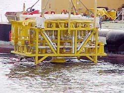
The Icarus tie-in system (Fig. 3) connected the flowlines to the manifold. Icarus is a remotely operated vehicle (ROV) installed tool that enables preinstalled flowlines to be pulled in, connected, and tested in a single subsea deployment.
The production manifold's two 11-in. production headers allow for round-trip pigging. The 6-in. test header enables individual wells to be tested, and hydraulically actuated ball valves in the 11 in. and 6-in. headers enable process isolation and round-trip pigging.
Twenty-four 41/16-in. hydraulically actuated gate valves allow each well to be connected to either the production or test header.
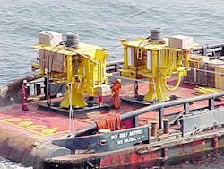
Installation of the manifold structure included the use of a 30-in. monopile and guide mast. The 30-in. monopile was preinstalled and maintains the manifold above the seafloor. The guide mast, installed in the 30-in. monopile before manifold installation, incorporates a nitrogen-charged shock absorber and external orientation helix.
The guide mast helps orient the manifold and reduces the vertical loads during the manifold landing operations.
ABB shipped component parts of the manifold to Sonamet's fabrication yard at Lobito for assembly and provided consultation to Sonamet during the construction and testing of the manifold assembly. A new dedicated duplex-steel fabrication shop facilitated the construction of the manifold pipe work, resulting in the manifold being completed 6 weeks ahead of schedule.
During manifold construction, inspectors reported only three minor weld defects out of the total of 300 welds.
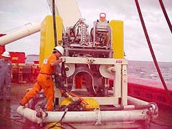
Each 1C satellite well has a 4 in. by 2 in., 5,000-psi horizontal tree designed to API PSL-2 and having a material class HH rating (Fig. 4).
The tree includes a concentric stepped internal profile for the tubing hanger, integral 51/8 in., 10,000-psi production master valve, integral 21/16-in., 10,000-psi annulus master valve, and an integral 21/16 in., 10,000-psi annulus access valve.
The 51/8 in., 10,000-psi production and 21/16 in., 10,000-psi annulus wing blocks are mounted outboard of the corresponding master valves. The production flow loop terminates in a 41/16-in. mandrel for connection to the manifold via a 4-in. flexible well jumper.
The annulus flow loop terminates in a 11/2 in. and 1/2-in. dual horizontal tie-in mandrel. The annulus is connected to a gas-lift distribution unit, via a gas lift and methanol supply jumper. The 1/2-in. line to the production bore allows for gas and methanol injection to the annulus.
Pressure and temperature sensors downstream of the choke and downhole monitor the production bore and annulus.
Production jumpers
The 4-in. flexible jumpers, with two vertically made-up DG connectors, connect the production tree to the manifold.
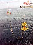
Two independently controlled lift lines and two independent running tools lowered the jumper assemblies to the seabed (Fig. 5). Guide wires and guide posts provided the primary alignment for the jumper installation tool with secondary alignment being provided by the gooseneck connector entering into the manifold guide funnel.
The jumper was connected to the subsea tree by lowering of the gooseneck connector into the tree-mounted guide funnel. A dedicated tree-mounted guide frame provided the primary guidance.
A ROV hot stab locked the gooseneck connectors to the manifold and subsea tree mandrels. The hot stab also tested the individual connector back seals.
Gas lift
Two gas-lift distribution units (GLDU) with integral umbilicals provide lift gas and methanol supplies to the subsea production trees. Each GLDU serves up to six producing wells and incorporates a detachable mud mat and four lifting points.
One can isolate gas flow to the individual wells by means of 11/4-in. bore, ROV actuated, quarter turn, needle valves.
A top-mounted guide funnel on the GLDU orients the gas-lift jumper running tools.
The FPSO supplies lift gas and meth anol to the individual GLDUs by a static umbilical, consisting of a steel-tube bundle, and a dynamic umbilical, consisting of a lay-up of thermo-plastic hoses that are reinforced by composite fibers.
The umbilicals are mounted to the bulkhead plate on the GLDU. A flexible dual bore gas-lift jumper assembly connects the GLDU to the subsea trees. The jumper includes 11/2-in. gas and 1/2-in. methanol lines and has ROV operable, dual-bore horizontal tie-in connectors.
CSO deployed the gas-lift jumper with two independently controlled winch wires and two dedicated ROV-operated running tools.
A stab tool landed the jumper into a funnel on top of the GLDU, and an ROV-operable API 17D Class 4 torque tool connected the jumper to the GLDU. After this connection, the jumper then was laid away to the subsea tree.
The installation process used a deployment sled to connect the jumper to the subsea trees. The sled landed near a tree enabling the ROV to fly the gas-lift jumper connector to the subsea tree. An API 17D Class 4 torque tool maneuvered and locked the gas-lift jumper to the subsea tree.
Subsea controls
The 1C production control system employs an open loop, multiplexed, electro-hydraulic, control system. Separate conductor pairs transmit electrical power and communications to the subsea equipment.
The control system is identical to that on the 1A and 1B centers. Control of the system is by a dedicated master control station linked to the FPSO's process control.
The FPSO is connected to the subsea distribution unit (SDU) by a dedicated 1C thermoplastic umbilical that provides for dual redundant low-pressure hydraulic fluid, dual redundant high-pressure hydraulic fluid, dual redundant electrical power and communications, downhole chemical injection, and subsea tree chemical injection.
The 1A, 1B, and 1C centers have individual umbilicals.
The SDU distributes hydraulic power, chemical injection, and electrical power and communications to the subsea trees by separate hydraulic and electrical flying leads, which were deployed by installation baskets using an ROV.
A hydraulic stab plate facilitated the connecting of the hydraulic flying leads to the subsea control module's mounting base. An API 17D Class 4 torque tool made up the stab plate.
ROV manipulators made up the electrical flying leads to the top of the subsea control modules. Length of the flying leads varied with the longest being 180 m.
A subsea control module, mated to a mounting base on the side of each tree, controls each subsea tree. One can deploy and retrieve the module with a dedicated ROV-operated running tool.
The subsea control module receives dual low and high-pressure hydraulic fluids via the mounting base. Shuttle valves consolidate the fluids in the subsea control module.
A single electrical flying lead and a top-mounted electrical conductive connector provides the dual-redundant electrical power and communications to the subsea control module. The module has a single subsea electronics module that provides control and allows for data acquisition from the subsea tree and downhole gauges.
Topside controls
The 1C development required the existing 1A infrastructure to be expanded to cater for the additional process facilities required for 1C. This required the hydraulic power unit (HPU) and communication system to be expanded to suit the new requirements.
The control system required software upgrades, an additional communication modem, an HPU expansion module, and an additional umbilical termination.
The Kuito production control system on the FPSO includes the subsea equipment's operator station, master control station, subsea power and communication unit, uninterruptible power supply, hydraulic power unit, and topside umbilical termination units.
The operator station is in the FPSO central control room and provides the operator interface for controlling and monitoring the 1A, 1B, and 1C subsea centers.
The master control station is located remotely from the operator station and provides the control and monitoring logic required to operate the HPU, surface modem units, and the individual subsea control modules. It communicates with the subsea control modules via the surface modem units located in the surface power and communication unit.
The FPSO emergency shutdown system interfaces with the master control station through hard-wired links.
The subsea power and communications unit incorporates multiple subsea modem units that generate separate electrical power and communications for operating the subsea control modules. An uninterruptible power supply connected to the master control station and surface modem units ensures continuous operations.
The skid-mounted HPU provides the subsea control modules with low and high-pressure hydraulic fluid. It generates 3,000 and 7,500-psi hydraulic pressure required to operate the subsea tree actuators and the downhole safety valves.
An onboard programmable logic controller (PLC) system controls and monitors the electric and pneumatic pumps.
Activation of the FPSO emergency shutdown system will inhibit the HPU pumps and vent the subsea hydraulic pressure.
Topside umbilical termination units connect the electro-hydraulic and gas lift-methanol injection umbilical to the HPU, chemical injection unit, and surface power and communication unit.
Flowlines
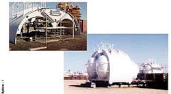
CSO's Le Trait plant in Normandy, France, manufactured the flexible flowlines and risers. The flexible lines were delivered on six reels and the three risers were installed on three mid-water arches (Fig. 6) in a lazy-S configuration.
All flowlines meet the requirements for a maximum water depth of 415 m. The two main design criteria at this depth are:
1. The collapse of the structure due to hydrostatic pressure.
2. Resistance to crushing due to high installation tension.
Subcontracts
Fabrication of permanent equipment, including the three mid-water arches and three gravity bases was through numerous subcontracts.
Sonamet in its Lobito construction yard fabricated the mid-water arches and gravity base.
A positive working relationship between CSO and Sonamet resulted in the equipment being delivered ahead of schedule.
The mid-water arches were a challenge because they had to be pressurized to 16 bar with nitrogen to allow their wall thicknesses and therefore their weight to be reduced so that they could be manufactured and installed at a 300-m water depth.
Umbilicals
DUCO Ltd., Newcastle (a member of the CSO group), produced the electro-hydraulic umbilical and the gas-lift risers, while DUCO Inc., Houston, manufactured the static portion of the gas lift umbilicals, which consists of a steel-tube bundle.
CSO shipped the static and dynamic sections to Le Trait for connecting them together.
Offshore installation
The original installation called for all major equipment to be mobilized from CSO's Le Trait yard.
This was revised in Spring 2001 after the decision was made to manufacture the manifold, mid-water arches, and gravity bases in Lobito.
For the installation work, CSO chartered the construction vessel DP Smit Pioneer.
Its large deck, nearly 160 by 30 m, accommodated all flowlines, umbilical, manifold, gravity bases, and mid-water arches in a single trip.
The 1.5-month installation schedule required the Icarus tie-in tool to make up three flowlines to the manifold.
The good performance of the Smit Pioneer and incorporated lessons learned from Kuito 1A and 1B led to efficient offshore operations.
Offshore operations started in Le Trait in early June 2001, with the loading of the 1C facilities on board the Smit Pioneer.
The load out of the Sonamet fabricated manifold, gravity bases, and mid-water arches in Lobito were also successful.
The vessel transited the 4,600 km from Le Trait to Gulf of Guinea in 3 weeks. This included two short stopovers, one in Le Havre for ROV wet tests, and the second in the Canary Islands for refueling.
The installation required some tricky interfacing of vessel schedules to mitigate the high risk of interference between the drilling rig, FPSO hookup activities, and the shallow diving support vessels.
Smit Pioneer completed the installation work in less than 40 days.
Because of the long swell in the Gulf of Guinea, it is recommended to use a heave-compensated crane to avoid weather stand-by while performing lifts close to maximum crane capacity.
Smit Pioneer used two Perry Tritech, Triton XL ROVs for the delicate subsea tie-ins of flowlines and jumpers. Overall ROV performance was good, with less than 2% downtime.
Interface with the ABB equipment went well because of the use of a full-size mock-up ROV during system integration testing and the incorporation of lessons learned from Kuito 1A and 1B.
Subsea construction work at the manifold area lasted less than 1 week, including the Icarus tie-ins. The Icarus tool took 3 days to connect to the manifold the two 9.5-in. production flowlines and one 6-in. test line.
CSO deployed the flexible and umbilical jumpers between the producing wells and the manifold with a technique it developed on a previous African pro j ect, the Zafiro field in Equatorial Guinea.
This part of the project hooked up three wells.
Because of the variety of risks to the personnel, equipment, and assets, safety was a critical aspect of the Kuito project. The implementation of appropriate health, safety, and environment measures during the operation was a continuous objective during the project, in particular with respect to the difficult working environment in which long working hours in the heat decreases safety awareness and tropical diseases are a risk for Western country citizens.
The author
Per Dyberg is a project manager for ABB Offshore Systems Inc., Houston. He was project manager on Kuito 1A, B, and C and previously worked on several projects off Norway. Dyberg has an MS in petroleum technology from the Institute of Technology in Norway.
