Drilling system combines composite-coiled tubing, hydraulic-workover unit
Based on a presentation to the International Association of Drilling Contractors and Society of Petroleum Engineers drilling conference, Dallas, Feb. 26-28, 2002.
The petroleum industry, historically, has drilled wells with steel pipe. Technology advances, however, have enabled engineers to design, build, and introduce a hybrid-drilling system that combines composite coiled-tubing technology with a hydraulic-workover unit.
By using composite pipe with embedded conductors, the system achieves uninterrupted real-time, two-way communication with the downhole tools, allowing a step-change improvement in the knowl edge of dynamic-wellbore conditions and in control over downhole systems.
Incorporating a hydraulic workover (HWO) jacking system to the drilling unit expanded the operating envelope to allow handling of jointed pipe for running completions, rotary drilling, fishing, wellbore preparation, and underbalanced operations.
The spooled-composite drillstring, to date, has drilled eight well paths with increasing degrees of difficulty.
Empirical data, gathered during these drilling operations, indicate that composite coiled-tubing materials yield significant gains in fatigue-resistance and general safety of the operations.
System development
Halliburton Energy Services Inc. and Statoil SA originally developed the Advanced Well Construction System (AWCS) based on advances in composite materials, telemetry, and system-control sciences.
The companies designed the AWCS phase of the hybrid drilling system to develop inaccessible reserves in mature North Sea fields.
Within 27 months from the feasibility study in late 1997 to completion of a testing and qualification program in early 2000, the companies produced a fit-for-purpose, digitally controlled system that uses advanced composite coiled tubing (ACCT), a carbon-fiber composite umbilical with embedded conductors, and a bottomhole assembly (BHA).1
AWCS's design features included reduced weight and space, smaller crew sizes, and the capability to drill difficult well paths.
Designers enabled the system with real-time, data-transmission technology so that personnel could make drilling decisions from anywhere offsite.
The properties of the composite pipe, allowing embedded electrical conductors, enable downhole data transmission rates to the surface that are several thousand times greater than conventional systems.
With this increased information rate, geoscientists can place the wellbore more precisely within the given hydrocarbon zone.
In addition, the capability of transmitting electrical power and commands through the pipe adds increased versatility and control of the drilling process, improved well control, and avoidance of hazardous conditions.
The technology enables collaboration between formation evaluation experts, drilling engineers, geologists, and geophysicists to improve the decision-making process and make decisions in real time regardless of the team's proximity to the drilling operation.
Drilling teams can guide advanced well paths with real-time updates of the earth model.
In exploration applications, the well construction team can find isolated and bypassed pockets of oil and gas by maneuvering the BHA through the subsurface. Real-time bottomhole data allow personnel to perform intricate geosteer ing remotely.
The addition of an HWO unit increased the system versatility for a broader range of operations. The new hybrid unit can run jointed pipe as well as coiled tubing.
The unit can drill at high angles, hit hard-to-reach formations accurately, and place the wellbore in the optimal position. The unit can push or pull the drillpipe, logging tools, or completion equipment into and out of the well, if required.
The HWO unit handles pipe-light conditions as a normal part of operation, from pushing completions into a deviated well, to performing underbalanced drilling or completions work.2
Engineers designed and built the hybrid-drilling unit with a zero-discharge mindset, accepting zero accidents, injuries, or losses.3 A zero-discharge system must be a well-designed, fit-for-purpose system.
Det Norske Veritas (DNV) offers verification that the base AWCS (control cabin, reel, power pack, injector) was built to NORSOK, EU, API, BS, ASME, ISO, NACE, and NPD applicable standards.
All other components were built to API and ASME specifications for Gulf of Mexico operations.
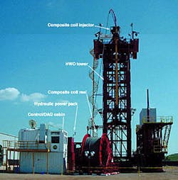
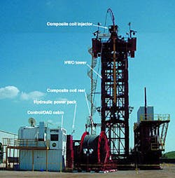
The equipment in the new drilling system includes a coiled-tubing unit, HWO unit, supporting tower structure, blowout preventers (BOPs), a fluid system, and the digital control and data-acquisition system, and ACCT and BHA (Fig. 1).
Control system
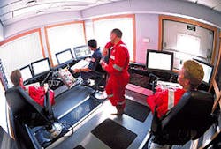
A three-man team operates the entire system from workstations in the control cabin (Fig. 2).
A driller runs the equipment and drilling operations, a systems engineer maintains the system integrity, and a geosteering specialist interprets the sensor data, builds a detailed subsurface map, and guides the well path accordingly. When required, personnel can perform any of these functions remotely.
Each work station has two high resolution, flat-screen monitors from which the operators can observe real-time data variables from both surface and bottomhole sensors, helping them to control the drilling process.1
The driller concentrates on the physical drilling process, while the geosteering engineer evaluates the formation characteristics to better steer the tool for an optimum producing wellpath. The stations are fully networked and interchangeable, allowing full backup.
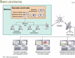
Fig. 3 shows how a job would be operated remotely. A satellite uplink provides data in real-time to an internet-linked system.
This two-way communication transfers well information securely, as required by the operator, to and from experts anywhere offsite.
The driller uses the control system to set or adjust drilling parameters such as weight-on-bit (WOB) and motor torque. Once the driller enters the desired operating set points and limits, the control system adjusts the pipe movement to maintain these parameters.
The integrated-control system uses a combination of both the surface parameters and the downhole measurements to optimize performance. For example, the control system monitors both the surface string weight and the downhole tension and compression measurement.
The control system will alert the driller to frictional drag changes during drilling to help reduce the risk of getting stuck. The control algorithms allow the driller to monitor trends and perform calculations, speeding up the decision-making process.
Coiled-tubing unit
The fully automated surface equipment, the ACCT with embedded conductors, and the BHA make up the major components of the system.
The surface coiled-tubing equipment consists of the reel, a power pack, and a 100K injector. Engineers designed the unit to ensure that major components are compatible with other coiled-tubing equipment. The operator could use a 60K injector rather than a 100K injector, for example.
The 100K injector head can withstand continuous 100,000-lb loads and 125,000-lb overpull. It is designed to snub up to 50,000 lb and can handle 1.5-5.5-in. pipe sizes.
The injector uses a split-beam design, allowing a full opening of 7.5 in. for BHA ease of installation, removing the injector from wellbore center.
Two optical encoders, mounted on the injector, perform the depth measurement. One encoder is mounted on a measuring wheel running on the tubing, while the second is mounted on the motor drive shaft.
The second encoder serves as both a backup and a check on slippage of the tubing in the injector. Load pins measure the string weight in both tension and compression.
A level sensor mounted in the area above the stripper serves as a small reservoir for the stripper lubricating fluid, which can be water when the composite coiled-tubing is in use.
The injector is mounted on a skidding table, which allows it to be skidded to the side for full access to the wellbore and HWO jack.
The reel is a simple split design with a cradle and spool (Fig. 1), which reduces weight for individual lifts and allows the pipe to be changed by switching spools. Engineers designed the spool to hold 21,000 ft of 27/8-in. or 17,000 ft of 31/8-in. coiled tubing.
The reel has a 12-ft diameter core that helps ensure compatibility with the strain constraints of the composite coiled-tubing. Fully integrated crash frames and walkways, designed into the reel and cradle, facilitate safe access to all areas for service and maintenance.
Redundant power-pack manifolds have both manually controlled valves and electro-hydraulic valves that allow the computer-controlled system in the control cabin to run the hydraulics. In case of electrical failure, crews can operate the unit manually.
A sound enclosure on the power pack reduces noise emissions, recorded at 1 m, to a maximum of 85 db.
Accumulator bottles, 150-gal capacity, control the BOP system. An air-over-hydraulic pump provides a backup source for charging the accumulator bottles.
Hydraulic workover unit
Combining the composite coiled-tubing drilling unit with the HWO unit expands the options that become available to operating companies.
The HWO unit can handle jointed pipe for completions, drilling, fishing, and wellbore preparation. The HWO hydraulic jack can pull 200,000 lb, is rated for a snubbing force of 100,000 lb, and can run pipe sizes up to 95/8 in.
The tower supports the weight of the jack and string, in the standard configuration, without additional weight being transferred to the wellhead.
A power rotating head, with torque rating of 11,000 ft-lb at 80 rpm, rotates the jointed pipe string. The rotating head and jack, located below the drill floor, reduces worker exposure to moving parts and allows more room on the drill floor for personnel to work safely.
The crew operates the HWO manually, with sensors measuring string weight, depth, rotary torque, and jack position, with the information made available in the real-time, control-system database.
A networked computer, in the basket, displays information from the database to the HWO operator.
A telescoping mast handles pipe, up to API Range 3 casing lengths. The drill floor has a "false rotary" for a small slip bowl and hand slips for running the BHA with the mast.
Made of multiple sections, the tower height can be configured for specific rig-up situations. The base sections of the tower, 24 ft high and open on one side, allow the tower to be skidded on and off the wellbore with a BOP stack present.
Each upper section is 8 ft tall and removable, to adjust the height. At its tallest, the drill floor is 76 ft. In addition, when clamped to rig beams, the tower can withstand 100 mph winds without guy wires. Guy wire points are available if the clamping system is not used.
Mud system
The modular mud system consists of four modules, which stacked together create three levels:
- Lower level is the tank.
- Middle level consists of two equipment modules containing the solids-control and gas-removal equipment.
- Upper level consists of an air-conditioned mud lab and 30 ft by 10 ft open area for chemicals storage.
With the tank divided into seven compartments, the active mud system has a total capacity of 450 bbl with a total volume of 520 bbl before overflowing.
Normal-mud flow is through the four largest compartments to allow for settling of solids, solids removal by centrifuges, gas removal by a vacuum degasser, and property adjustments in the fluid parameters by mixing in chemicals.
The trip tank is a 10-bbl compartment, and the mix tank is a 25-bbl compartment. A diverter ditch in the top of the tank allows for flow from the shakers to be diverted to the different compartments.
For example, crews can circulate a slug or pill through the well and recapture it in the mix tank. The overflow of all of the individual compartments is back into the main volume, reducing the chance for spillage.
The solids-control equipment includes two 8-G shakers, and two centrifuges for barite recovery and solids removal. The gas-removal equipment includes a 48-in. diameter gas separator and a vacuum degasser.
Three centrifugal pumps mix and pump the mud and provide charge pressure to the downhole mud pumps. The centrifugal pumps are mounted on the tank and connected to common suction and discharge manifolds.
Contained within the boundaries of the tank, the pump and manifold configurations reduce rig-up time and minimize spillage risk.
The crew can change valve settings remotely with the air operators fitted to the circulation valves and the air valve control panel located next to the mud-mixing hopper.
When mixing chemicals, personnel can monitor tank levels and mud properties from a computer at the mud hopper. The mud system includes level transducers in each tank and gas detectors above the shakers.
The system measures flow rate, mud density, and mud temperature, both in and out of the fluid system. The mud system stores data from the sensors in the real-time control database and are available on the network.
Composite coiled tubing
The advanced composite coiled tubing supplier manufactures the pipe in a continuous coil using a tough carbon-fiber laminate and other advanced material.
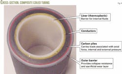
Fig. 4 shows the tubing cross-section. Under most drilling conditions, the pipe is nearly buoyant, which significantly reduces weight and drag compared with steel tubulars.4
Use of the reeled pipe eliminates pipe-handling operations that are required for jointed steel drill pipe. Composite coiled tubing is inert to most chemicals and does not corrode.5
The embedded conductors in the pipe enable two-way communication with the BHA.
Through various sensors, the BHA measures the annulus pressure, delta pressure across the motor, WOB (tension and compression), temperature survey, directional gamma ray, and resistivity.
Motors in the BHA, receiving commands from surface, control the backpressure valves, electric disconnect, actions of the tractor, and the bend angle of the 3D tool.
Bottomhole assembly
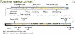
Engineers designed the surface equipment, composite tubing, and downhole tools as a single system. Just as the industry designed rotary drilling rigs to run rotary bits, the surface system was designed to run composite pipe and a special BHA (Fig. 5).
The two most unusual features of the BHA are the elimination of most downhole electronics and the introduction of a downhole propulsion unit or "tractor."
Conductors embedded in the wall of the composite pipe supply the BHA's power and telemetry requirements.
Accordingly, the BHA does not need batteries or downhole turbines to supply power, no mud pulser to transmit sensor readings to the surface, and no memory modules or downhole processing to manage data.
Tool designers built functionality into the BHA to take advantage of the two-way communications with the tool assembly.
For example, the driller can change the steering tool orientation continuously, which is an important consideration for geosteering applications. He can also open and close circulation ports to redirect flow when required.
The system introduces two new formation evaluation tools: a resistivity sensor that generates and transmits 20 depths of investigation and a focused gamma-ray sensor that provides multidirectional gamma readings.
Tool designers added a highly sensitive casing-collar locator, downhole pressure tool, tension-compression sensors, and directional sensors to manage wellbore and drilling dynamics.
The BHA introduced a downhole tractor designed to apply WOB and to pull the BHA into the open hole, rather than pushing it with the coiled tubing from the surface.
Operated with electronic commands from the surface, the tool works in concert with surface equipment to manage pipe stress.
Acknowledgments
The authors would like to thank Halliburton and Statoil for their support in the development of the hybrid system, and BP PLC for support during system testing.
References
- Marker, R., et al., "Anaconda: Joint Development Project Leads to Digitally Controlled Composite Coiled Tubing Drilling System," SPE paper 60750, presented at the SPE/ICoTA Coiled Tubing Roundtable, Houston, Apr. 5-6, 2000.
- Coats, E.A., and Farabee, M., "The Hybrid Drilling Unit: An Overview of an Integrated Composite Coiled Tubing and Hydraulic Workover Drilling System," SPE paper 74349, presented at the SPE International Petroleum Conference and Exhibition, Villahermosa, Feb. 10-12, 2002.
- Coats, E.A., Preston, D., and Figenschou, A.N., "An Overview of the Global Health, Safety, and Environmental Program for Advanced Well-Construction Systems," SPE paper 60757, presented at the SPE/ICoTA Coiled Tubing Roundtable, Houston, Apr. 5-6, 2000.
- Berning, S., Isennock, C., and Coats, A., "Composites Extend CT's Applications," American Oil and Gas Reporter, September 1998, Vol. 41, No. 9.
- Dalton, C., Paulk, M., and Bittar, M., "Real-Time, Time-Lapsse Resistivity Logging with a Wired Composite Tubing," SPE paper 74380, presented at the SPE International Petroleum Conference and Exhibition, Villahermosa, Feb. 10-12, 2002.
The authors
E. Alan Coats is business development manager and global technical consultant for Halliburton Energy Services Inc. He has been involved in the hybrid drilling system development since its inception. Coats has worked in various technical and managerial positions with Otis and Halliburton since starting his career in 1975. He is a member of the Society of Petroleum Engineers.
Mark Farabee is surface equipment manager for Halliburton Energy Services Inc. He is a registered professional engineer with 10 years experience designing oil-field service equipment. He received BS and MS degrees in agricultural engineering from Oklahoma State University, Stillwater.
