Selection method addresses thermowell integrity
An improved thermowell selection method reduces the risk of thermowell misapplication and failure that result from flow-induced vibration.
It is based on a principal stress model of the thermowell and uses allowable-stress data as defined in the relevant piping codes. Its benefits are demonstrated by evaluations of three, case-study failures taken from gas pipeline applications.
Modern thermowells are extremely reliable. This is largely due to the use of high-strength, corrosion resistant materials and improved manufacturing. But it would be incorrect to suggest that they cannot fail.
For example, the risk of thermowell fatigue has reemerged as a critical issue in the case of temperature-compensated, ultrasonic flow measurements in which there is an emphasis on elevated flow velocities to improve measurement rangeability.
In any discussion of thermowells' failures, their apparent reliability is seen as proof that current design standards are adequate. This point is well taken, but confidence in these standards is shaken when published accounts of thermowell failures are pulled together in a systematic comparison.
Contrary to our initial expectations, thermowell failures are evenly distributed across all thermowell design types. It makes little difference whether straight, stepped, or tapered shank designs are used; they are all susceptible to failure if misapplied. Even extended surface (finned) designs are not immune.
Additionally, failure is not confined to corrosive or extremely high-velocity services. In fact, many have occurred in quite ordinary applications. It is significant that nearly a third of the published accounts have occurred in applications related to the collection, processing, and transport of high-pressure gases, a service not normally seen as severe.
The Murdock stress model1 and its companion ASME Performance Test Code (PTC) 19.32 have played a key role in reducing the incidence of catastrophic failures. Although specifically developed for high-pressure steam applications, they have been used as an "equivalent steam basis" for defining the minimum strength requirements for all thermowells.
Selection; code limits
Thermowell selection is usually driven by the measurement needs once the static pressure rating and materials of construction have been sorted out.
The dominant concerns are maintaining adequate sensor immersion and sensor placement within the process and, to a lesser extent, a need to minimize conduction errors.
These factors are dealt with in the form of application rules that emphasize the needs of older filled-system temperature sensors. One such rule required that all thermowells extend into the central third of the pipe. This often clashed with manufacturers' velocity ratings, and the tendency was to opt for accurate measurement; in other words: ignore the velocity ratings.
This approach led to a proliferation of high aspect-ratio designs that were and are vulnerable to flow-induced resonance.
Evidence for this is seen in the sort of catastrophic thermowell failures reported in high-pressure steam applications before 1961.3
Although the Murdock stress model and PTC 19.3 have greatly benefited thermowell design and application, the Murdock model is far from comprehensive.
The two models correctly emphasize the importance of lateral stiffness as a controlling factor in avoiding flow-induced resonance, in arbitrarily restricting consideration to shear failure, but they only establish collapse strength under cross-flow conditions. Such a restriction is justified only in the case of relatively short, thin-walled thermowell designs.
Additionally, in high-density fluids, the simplified vortex-shedding model used in the Murdock analysis is no longer adequate.
When a more comprehensive vortex-shedding force is included, the velocity rating in liquids can be reduced by as much as 50%.
This has important consequences in liquids and high-pressure gases because it means that failure can occur at surprisingly common fluid velocities.
In spite of these discrepancies, thermowells designed to PTC 19.3's strength minimums, on a representative steam basis, successfully cover a majority of industrial applications.
There are no statistics dealing with the effectiveness of traditional thermo well-selection methods or the impact of their use on rates of failure within the context of PTC 19.3 minimums.
An informal survey of thermowell applications where traditional selection rules had been used found that some 20-30% of the applications was exposed to low-velocity resonance with little or no threat to the mechanical integrity.4
An additional 1-3% of these applications was exposed to resonance at higher velocities, with peak stress levels in the range of one-fifth to one-third the yield strength.
Finally, a very small number of applications (less than 0.1%) were exposed to severe application stresses, at times exceeding the yield strength of the material.
As a rule, the risk of failure increases once the service stresses exceed some 20-30% yield strength. A surprising number of thermowells are therefore at risk of failure or at least reduced service life.
Vortex shedding
Under static conditions, thermowell design is controlled by the hoop stresses in the thermowell shank and the radial stresses in the tip.
For thick-walled, drilled bar stock designs, these stresses are so small that static pressure failure of the shank is practically impossible.
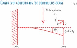
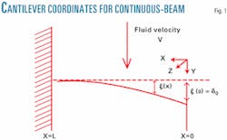
Under flowing conditions, the localized bending stresses control. The most important of these stresses are those produced by conventional drag and vortex-shedding forces acting to bend the thermowell (Fig. 1).
The flow-induced bending stresses are longitudinal and greatest on the outside surface of the thermowell. If the fluid forces were static, then the thermowell would be characterized by an easily calculated windage limit where the thermowell would simply fold-over.
This can only occur in cases in which the natural modes are not excited to resonance and the fluid velocity is extremely high. In practice, most failures occur at much lower fluid velocities, usually the result of flow-induced resonance.
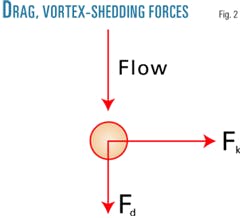
The fluid forces acting on the thermowell are directed along the flow direction (drag) and transverse (lift) to it (Fig. 2).5 These can be represented as vectors acting on the centerline of the thermowell, as expressed by Equation 1 in the accompanying box.
Averaging Equation 1over the thermowell span-while invoking a coherent vortex-shedding process based on the vortex-shedding rate at the tip-results in a conservative estimate of the excitation forces and resulting bending stresses.
These assumptions result in a lower bound estimate of the conditions that lead to stress failure.
Repeating the calculation with the vortex-shedding rate based on the root diameter establishes an upper bound on these conditions.
Actual failures can be expected to occur between the two limits. It is important to establish the complete range of operating conditions for the thermowell, from start-up to emergency conditions.
The vortex-shedding rate is given by ωk=2π SV/D. The Strouhal number is S~0.22, and the force coefficients, CD, Ck ~1, and Cd~0.1, are constants. This is in keeping with modern interpretations of the vortex-shedding process.
In the slender beam, small-amplitude limit, the in-line and transverse responses can be solved by conventional analysis methods. Fortunately, the two responses have identical mode structures and critical frequencies, so the solutions only differ in their respective excitations.
Since the in-line force cycles at twice the rate of the transverse force, the combined response exhibits two velocity criticals for each bending mode: in-line and transverse resonance. The in-line critical occurs at half the velocity of the transverse resonance.
Higher order modes can also be excited, although the degree of coupling between the fluid and the thermowell is smaller.
With nonsymmetric or nonuniform shank designs, the enumeration of the various modes is complicated by the fact that the transverse and in-line modes of separate modes may over-lap.
Because the elastic response of the thermowell and the vortex-shedding process are so closely coupled, the actual vortex-shedding process is extremely nonlinear and can be expected to be captured or locked-in to the structural resonance of the thermowell. This capture takes place as the vortex-shedding rate approaches a natural frequency of the thermowell.
As the beam responds, the vortex-shedding rate tends to settle onto the resonant frequency of the beam and remains locked-in for a considerable range of fluid velocities. In effect, the linearized response can only represent a capture probability and an estimated peak stress.
Thermowell stresses
The flow-induced stresses are easily modeled as a distributed force acting on a flexible beam. While the static pressure stresses control rupture strength of the thermowell, it is bending stresses that dominate its velocity rating. The pressure stresses are circumferential, while the flow-induced stresses are in the form of longitudinal bending stresses.
These are greatest at the base of the thermowell and distributed about the neutral axis as with any transversely loaded beam.
The peak stress occurs at the base of the thermowell, on the outside surface, and has the form shown in Equation 2.
The positive sign is used for the peak stress on the downstream side of the beam, and the negative sign is used for the peak stress on the upstream side of the thermowell.
The longitudinal stress components, all taken as positive quantities, are Sl (hydrostatic pressure), SD (drag), Sd,(oscillating drag), and Sk (oscillating lift), which for a static pressure, Po, are given by Equations 3-6.6
These equations are not as imposing as they seem; the summations represent a net magnification ratio for the respective in-line and transverse responses. The individual modes are characterized by the modal amplitudes, ci, natural frequencies, ωi, and relative damping, vi. Only the lower order modes are important; so the summations are quite manageable.
The stress amplitudes (σβ) are proportional to the aerodynamic pressure and are identical with an equivalent static stress calculation.
For example, the stresses for straight shank designs have the form σβ = πfCβD2L2V2/8I and are simply an application of the traditional cantilever, beam stress formula.
Once the static stress (zero frequency) amplitudes are known, all that remains is a calculation of the modal coefficients using any of the standard methods.
The Murdock analysis roughly corresponds to having ignored the possibility of in-line resonance and limiting consideration to a single critical frequency.
Even without full knowledge of the natural frequencies of the thermowell or the various modal constants, the static windage stress is bounded by ~σD, and the peak resonant stress is bounded by &tilde'σD/2ζ. To a crude first approximation, the windage stresses and an estimate of the minimum damping parameter are adequate to define the service stresses of the thermowell.
Design criteria
The Murdock stress model includes static pressure, conventional drag, and oscillating lift but focuses only on primary stress failure, the rupture stresses of the thermowell under high-velocity conditions.
In effect, it limits consideration to the peak shear stresses on the interior surface of the thermowell while ignoring the bending stresses on the exterior where the process environment can degrade fatigue strength.
As described earlier, when both primary and secondary stress failures are considered, the longitudinal bending stresses invariably control. In other words, localized tensile failure occurs long before the shear limit is reached.
Not surprisingly, most if not all reported thermowell failures appear to result from secondary stresses developed in bending.
For design, the sum of the static stresses caused by pressure and drag should not exceed the maximum allowable working stress of the material (MAWS; Equation 7).
Additionally, the high-cycle, dynamic stress components should not be allowed to exceed the fatigue allowable stresses (Equation 8).
This new criterion is more restrictive than that used previously6 but is recommended for those cases in which cyclical stresses dominate and corrosion is present. Allowable tensile stresses (MAWS) for common materials are tabulated in the piping codes.7 The piping code rules may be consulted to estimate the fatigue allowable stress in the absence of actual data.
Pipeline examples
The following examples characterize the potential for failure in pipeline and gas-processing applications. They are part of a larger collection of documented thermowell failures that includes gas, liquid, and steam services.
None of these failures was adequately explained by current thermowell standards, and all of them could have been avoided by use of an improved stress model and an appropriate design criterion.
Finite-element techniques are used to develop the dynamic stresses.8 This avoids the ambiguities inherent in poor critical-frequency estimates and allows a design-specific prediction of the thermowell response. For convenience, the mechanical properties of Type 316 stainless steel are used and the maximum allowable stress taken from ASME B31.3 (Process Piping).
The fatigue factor (K) is arbitrarily set at 50%. A damping factor of ~0.30% is used, recognizing that the worst-case resonant stresses can be larger by a factor of six to ten.9 10
The first example is a straight-shank thermowell in gas-processing service. The thermowell is 15-in. (375 mm) long, and the service velocity was 70 fps (21 mps).
In this case, process leakage originated from a fatigue cracking at the base of the thermowell and it had been in service less than a year.
As is common with many failure reports, the details of the design and the process flows are fragmentary and in some cases ambiguous. The stress calculation is performed on an air-basis.
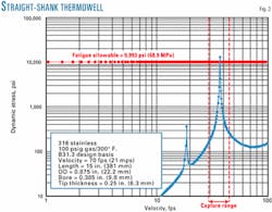
The dynamic stresses for a drilled bar stock design are shown in Fig. 3. They are characterized by an in-line resonance occurring at about 18 fps and a transverse resonance at about 37 fps. A representative capture band of 20% on either side of the transverse resonance is indicated.
Resonance can occur anywhere within this band, and the peak stresses easily exceed the fatigue-allowable stress but can easily exceed the maximum allowable stress at lower damping limit. With bending stresses concentrated at the base of the thermowell, localized failure (cracking) is expected, which was indeed the case.
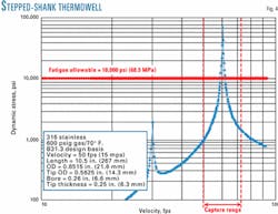
The second example is for a stepped-shank thermowell on the inlet of a compressor in gas pipeline service.11 The service pressure, temperature, and pipe size were inferred from the data given.
The thermowell had a length of 10.5 in. (267 mm) and the fluid velocity was 50 fps. The thermowell appears to have been a flanged design. No installation details were given, but use of nozzle-type installations modifies the boundary condition for the thermowell and effectively reduces the velocity at which flow-induced resonance can occur.
The dynamic stresses (on a methane basis) are characterized by in-line resonance at about 30 fps and a transverse resonance at about 60 fps.
The in-line resonance produces significant stress levels but not severely enough to damage the thermowell, even when the uncertainty in the damping factor is taken into account.
The second critical is more significant and occasioned by stress levels that approach the ultimate tensile strength of the material. While the fluid velocity is within the capture range of the resonance, it is also noted that the peak fluid velocity even in the case of well-developed turbulent flows can be higher than the mean velocity. Such an increase easily accounts for the possibility of sustained resonance.
This thermowell lasted less than a year with nonspecific fatigue failure occurring near the base. It was successfully replaced by a stiffer, tapered-shank design that did not resonate in the normal flow range.
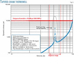
The third example involves a tapered-shank design located in a gas-separation unit in the discharge of a refrigeration compressor.12 The thermowell was 8 in. long. The fluid velocity at the time of thermowell failure was initially 42 fps but increased to 60 fps as a result of capacity increases.
Repeated failures were involved, at least until the thermowell length was reduced.
The dynamic stresses (Fig. 5) are calculated on an ethane basis and characterized by an in-line resonance of about 53 fps with an estimated peak stress of about 3,500 psi.
Although this is well below the fatigue allowable stress, given the uncertainty in the damping parameter (shown as a dashed ellipse), the thermowell is clearly at risk of misapplication.
It was replaced by a shorter one (6 in.) in which the flow criticals occurred were well above the expected flow condition.
This case is also important in that the vibration spectrum of the thermowell was recorded by means of a head-mounted accelerometer.
Although such a recording can only be expected to provide indirect evidence of the thermowell stress response, it clearly indicated a strongly developed resonance centered at 505 hz with the double side-band structure characteristic of large amplitude, in-line resonance, with an average fluid velocity of 60 fps.
No ready explanation appeared for the discrepancy with the PTC 19.3 prediction of 361 hz and the observed resonance.
The finite-element calculation predicts a natural frequency of 515 hz, once thread engagement is taken into account, and predicts in-line resonance at about 52 fps.
This predicted critical is roughly midway between the initial and final service velocities and well within the possibility of resonant capture. Given the uncertainties in the damping parameter, the peak stress can easily exceed the fatigue allowable and would have required that an alternative selection be made in the design stage rather than after the fact.
As a rule, any resonant condition in the normal range of flow conditions should be avoided.
On a cautionary note, all of these examples involved flammable hydrocarbons with the fluid escaping from inside the thermowell. This leakage is initially confined to the conduit and wiring system and may escape notice, but it can have serious consequences as an explosion hazard and risk to personnel.
Acknowledgments
Dean Ripple of the National Institute of Standards and Technology (NIST) helped in addressing thermowell safety in a more balanced and constructive manner. NIST is a nonregulatory federal agency within the US Commerce Department's Technology Administration.
References
- Murdock, J.W., "Power test code for thermometer wells," ASME Journal of Engineering for Power, October 1959, pp. 403-16.
- ASME Performance Test Code, PTC 19.3: Temperature Measurement, 1974.
- Love, T.J., "Thermometer-well failures traced to vibration," Power, February 1961, pp. 80-81.
- Bartran, D.S., Frikken, D.R., Kinsey, J.M., Schappelle, R., and Yee, R., "Flow induced vibration of thermowells," ISA Trans., Vol. 38, 1999, pp.123-32.
- Blevins, Robert D., "Flow-induced vibration," Malarbar, Fla., Krieger Publishing Co., 1994.
- Bartran, D.S., Frikken, D.R., Kinsey, J.M., Schappelle, R., and Yee, R., "Static and dynamic stresses of practical thermowells," ISA Trans., Vol. 39, 2000, pp. 133-42.
- ASME Code for Pressure Piping, B31.
- Thompson, W.T., and Dahleh, M.D., Theory of vibration, 5th Edition, Upper Saddle River, NJ: Prentice-Hall Inc., 1998.
- Morshita, M., and Dozaki, K., "History of flow-induced vibration incident occurred in Monju," ASME PVP, Vol. 363, 1998, pp. 103-08.
- Blevins, R.D., Tilden, B.W., and Martens, D.H., "Vortex-induced vibration and damping of thermowells," ASME PVP, Vol. 328, 1996, pp. 465-83.
- Balhaddad, A.S., "Thermowell failure analysis," Vibrations, Vol. 11, No. 1, 1995, pp. 8-9.
- Permana, Y., "Thermowell failure as a result of vortex shedding phenomena," Vibration Institute, Proc., June 1995, pp. 55-59.
The authors
Davis S. Bartran ([email protected]) is an instrument engineering specialist for Monsanto Enviro-Chem in Chesterfield, Mo. He specializes in process instrumentation and has more than 25 years' experience in the manufacturing, process chemical, and petrochemical industries. He holds a BS in electrical engineering from the University of Houston, a PhD from Rice University, and is a registered professional engineer in Texas.
Donald Frikken is an engineering fellow for Solutia Inc., St. Louis, Mo. He has more than 30 years' experience in design and troubleshooting of piping and equipment in the chemical process industry. Frikken is also an ASME fellow and a member of several ASME codes and standards committees. He holds a BS in mechanical engineering from Kansas State University and an MS in civil engineering from the University of Missouri-Rolla.
Richard Yee is a senior piping engineer for Monsanto Enviro-Chem, Chesterfield, Mo. He has more than 25 years' experience in piping system design and troubleshooting, development of piping system, construction specifications, and piping flexibility analysis. He has a BS in mechanical engineering from the University of Arizona and is a registered professional engineer in Missouri.
