Method optimizes hydraulics with PDM and bit
To meet the challenges of extended-reach drilling, deep and ultradeepwater wells, and horizontal completions, the drilling industry has dramatically increased its use of downhole positive displacement motors (PDM) during the past few years.
With these wells pushing the limits of rigs and equipment, it is imperative that operators use motors optimally in the system.
More often, however, drilling engineers do not include downhole motor pressure-loss calculations in the overall hydraulic optimization and bit-nozzle selection with the available pump power.
To make the system more effective, engineers must take into consideration various motor and drilling parameters for hydraulic optimization. The key to an improved drilling system is a unified approach that encompasses both the motor and bit.
Inclusion of the motor allows operators not only to calculate optimal flow rate and horsepower as a function of motor configuration but also to select the appropriate motor design based on desired parameters.
Furthermore, to maximize bit hydraulic horsepower fully, engineers must treat motor horsepower as a separate and important parameter. Motor configuration and weight on bit (WOB) strongly determine the pressure drop across the motor.
WOB, motor pressure loss
The differential pressure across the motor is directly proportional to the weight applied to the bit.
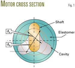
Equation 1 gives the mechanical horsepower from torque and rotational speed, while Equation 2 gives hydraulic horsepower for a multilobed motor (accompanying box). Fig. 1 shows the cross-sectional view of a two-lobe motor.1
Combining an overall motor efficiency relationship with Equation 2 generates an expression for torque in Equation 3. Equation 4, in turn, converts the expression into the relationship for pressure drop across the motor as a function of WOB.
The hydraulic horsepower available at the bit relates to the total circulating differential pressure of the system less the parasitic losses and the differential pressure across the motor, as in Equation 5.
The parasitic losses, Δppar, include drillstring, annular, and surface line pressure losses.
For turbulent flow, a power law equation satisfactorily represents the relationship between these pressure losses and flow rate, as shown in Equation 6. In the equation, K is a constant and s is an index indicating the degree of turbulence in the circulating system.
Engineers determine the coefficients of K and s by conducting rig pump tests with the bit off bottom. The tests require a minimum of two circulation flow rates, with the corresponding standpipe pressures, to estimate the coefficients.
For non-sealed motor bearings, a small percentage of circulating fluid passes through the mechanical seals, acting as coolant and lubricating the bearing assemblies. The drillbit flow rate, therefore, may not be the same as the mud-pump circulation rate.
To account for other split flows in downhole components, Equations 7 and 8 present generalized expressions for calculating the K and s coefficients for multiple-flow paths, where a is the bypass flow ratio or the ratio of the diverted flow in the downhole tools to the total pump flow.
Engineers select the flow rate and total flow area of the bit nozzles to use the available pump pressure fully, i.e., for the given solution, the sum of the parasitic losses, pressure drop across the motor, and the pressure drop over the bit equal the maximum pump pressure.
This means that after engineers determine the true optimum flow rate, they may increase the rate slightly to use all available pump pressure.
In a similar manner, Equations 9 and 10 present the relationship between flow rate and optimum horsepower and optimum impact force, respectively.
Equation 11 is the average rate of penetration as a function of WOB and bit rotation speed. Equation 12 gives the empirical relationship for the power required for drilling.1 2
These two equations assume that the formation is macroscopically homogeneous, hole cleaning is adequate, and the rig is drilling a vertical wellbore.
Using the above equations, operators can calculate the optimum flow rate that will maximize the rate of penetrations within the available pump pressure and power.
Optimization example
An example illustrates the calculations involved to optimize drilling parameters. Table 1 lists the wellbore and drilling operational details, calculation parameters, and the PDM configuration.
Equation 4 calculates the pressure drop across the motor for various values of WOB. In the example, the pressure drop for a WOB of 6,000 lbf is 185 psi, as calculated in Equation 13.
Fig. 2 shows the plot of power per area through the bit for a range of flow rates, varied total-flow area (TFA), and WOB for a particular motor configuration, i = 1/2.
The following steps explain a procedure to determine the TFA, and pump rate required, to maximize bit-power per area.
- Determine the pump rate on the X-axis, corresponding to the maximum power per area shown in the left Y-axis. If the rig pumps are not capable of producing the pump rate, use the maximum rate the pumps can produce.
- Determine the TFA from the right Y-axis, corresponding to the pump rate determined in step 1.
In a similar fashion, rig personnel can repeat the calculations for different motor configurations if operating characteristics dictate a lower bit rotational speed and higher operating torque.
The pump rate begins at zero and increases until the flow rate results in parasitic pressure losses equal to 100% of the total system pressure loss, in which the latter case results in zero pressure loss at the bit and motor.
Also apparent from Fig. 2 is that as the weight on bit increases, the flow rate increases when the maximum power per area of the bit shifts to the left and the corresponding total flow area required also increases.
Impact force, flow rate
From the calculations, nozzle sizing without including WOB may result in the lower power per area. Operators should, therefore, select a WOB operating window to estimate the total flow area and achieve the maximum power per area.
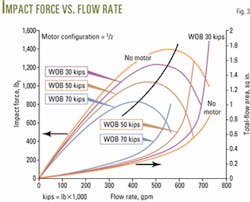
Engineers can use Fig. 3 to determine the impact force of the fluid through the bit for a range of flow rates, WOB, and varied total flow area (TFA). Use of the following steps can determine the TFA and pump rate required to maximize the impact force at the bit.
- Determine the pump rate on the X-axis, corresponding to the maximum impact force on the left Y-axis. If the rig pumps are not capable of producing this rate, use the maximum rate the pumps can produce.
- Determine the TFA from the Y-axis (on the right) that corresponds to the pump rate determined in step 1.
ROP vs. WOB
The power per area behavior also occurs in the maximum impact force calculations. Noninclusion of WOB in the analysis not only results in lower impact force but also results in improper sizing of the nozzles.
Fig. 4 shows ROP for various WOB values and also the ROP plots for various motor configurations.
Maximum ROP decreases with the increasing number of motor lobes. Also, the maximum ROP occurs with increased WOB, for each higher motor configuration.
In addition, Equation 10 demonstrates that the calculations strongly depend on the drilling parameter exponents, which in turn rely on the formation characteristics under consideration.
ROP, flow rate
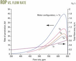
Fig. 5 shows ROP variation as a function of flow rate, given various motor configurations.
Operators can achieve more realistic estimates of the optimum flow rate if they include the downhole motor in the calculations.
The results suggest that noninclusion of WOB in the analysis causes over estimation of the nozzle size required to achieve the given criterion of power per area or impact force. Also, according to the calculations, nozzle sizing depends on the configuration of the motor in use.
The rate of penetration prediction is restricted to vertical wells. The sensitivity of the results suggests that one should use caution when making predictions involving maximum ROP, as the bearing load may restrict applying the desired WOB.
References
- Samuel, G.R., Miska, S., and Volk, L., "Analytical Study of The Performance of Positive Displacement Motor (PDM): Modeling for Incompressible Fluid," paper SPE 39026, presented at the Fifth Latin American Caribbean petroleum conference, Rio de Janeiro, Aug. 30-Sept. 3, 1997.
- Samuel, G.R., and Miska, S., "Optimization of Drilling Parameters with the Performance of Mutilobe Positive Displacement Motor (PDM)," paper SPE 47791, presented at the Asia Pacific drilling conference, Jakarta, Sept. 7-9, 1998.
The authors
G. Robello Samuel is a technical advisor in Landmark Graphics Corp.'s R&D division and is currently the technical and engineering lead for the well planning application suite. He serves as a technical editor for SPE and ASME. He is the chairman of the SPE's multilateral-technology, technical-interest group and member of the SPE well logging committee. He holds a BS and MS in mechanical engineering from the University of Madras and MS and PhD in petroleum engineering from the Tulsa University.
Glenn R. McColpin is currently product manager for Landmark Graphics' well planning software suite. He joined Landmark's drilling software group in 1994 after spending 5 years with Sperry Sun Drilling Services in MWD operations. He holds a BS in petroleum engineering from the New Mexico Institute of Mining and Technology, Socorro.


