Low capital revamp increases vacuum gas oil yield
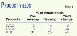
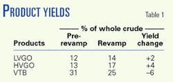
In 2000, Repsol YPF's Lujan de Cuyo, Argentina, refinery completed a vacuum unit revamp that increased total gas oil yield by 6% on whole crude while maintaining heavy vacuum gas oil (HVGO) product quality (Table 1).
The revamp also improved run length1 2 and increased feed rate from 55,000 to 70,000 b/d. The increase in HVGO yield corresponds to a 68° F. higher true boiling point (TBP) cut point. The revamp had a simple payout of less than 6 months.
Revamps are highly constrained by existing equipment design and actual equipment performance.3 Standard grassroots project management practices that use a hierarchal approach using several equipment specialists working independently do not work well in a revamp. These approaches often miss low-capital opportunities that arise because of integrated system effects.
Finding a low-capital solution requires comprehensive measured data from the unit,4 experience with vacuum unit revamps, and sufficient equipment knowledge to evaluate all components in an integrated system. Rigorous modeling and equipment performance evaluations of the heater inlet to ejector outlet as a single system were done early in process engineering.
The revamp replaced one of the two first-stage ejectors, and implemented minor changes to the heater and more extensive changes to the column internals. System pressure, oil partial pressure, and operating temperature were all manipulated to better use the existing equipment.
Major equipment performance ultimately determines maximum operating temperature and minimum pressure. Cursory computer studies that recommend a lower operating pressure and higher temperature may not identify all significant equipment limits that influence scope and cost.
Attempts to decrease operating pressure can cause massive vacuum tower bottoms (VTB) entrainment into HVGO if the flash-zone design is poor. Maximum operating temperature may be limited by heat flux imbalances due to poor tube layout or poor low-NOx burner performance. These details must be thoroughly understood and quantified during the conceptual process design (CPD) stage; otherwise, the revamp may not meet its processing objectives.
Background
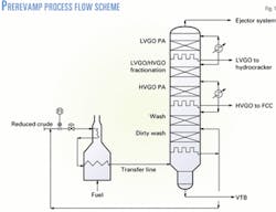
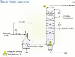
Before the revamp, the vacuum unit (Fig. 1) experienced a low HVGO TBP cut point, black HVGO, short run length, and poor light vacuum gas oil (LVGO)/HVGO fractionation efficiency. In this refinery, LVGO and HVGO products are used as hydrocracker and FCC unit feedstocks, respectively.
The LVGO product yield was limited by poor fractionation efficiency between LVGO and HVGO products. LVGO product quality is important because high asphaltene, concarbon, or metals result in catalyst poisoning, poor product yields, and shorter hydrocracker run lengths.
Attempts to raise the feed rate resulted in a rapid increase in HVGO concarbon, metals, and asphaltenes above maximum specifications.5 6
Poor LVGO/HVGO product fractionation resulted in a 85° F. TBP 95-100% tail on the LVGO product that limited yield.
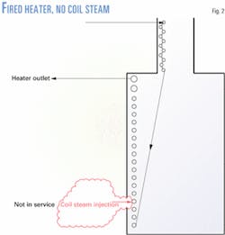
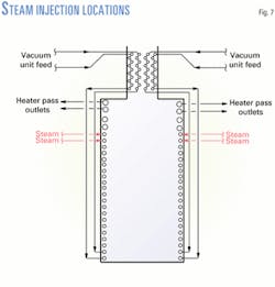
The maximum heater outlet temperature was set at 750° F. to minimize coking and maintain reasonable heater run length. The original heater design had coil steam injection near the front of the radiant section (Fig. 2)but injecting steam would increase vacuum tower operating pressure and reduce HVGO product yields; therefore, it was not used.
Key success factors
The revamp required only low-cost modifications because the vacuum unit had an underutilized charge heater and column, poorly designed column internals, and a damaged first-stage ejector.
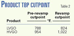
The revamp increased gas oil yield by 6%. Table 2 shows a comparison of pre and postrevamp product cut points. Unit run length also improved despite a higher operating temperature and lower column operating pressure.
Key success factors for the vacuum unit revamp included:7 8
- Early identification of low-capital cost opportunities.
- Thorough understanding of unit operating conditions and equipment interdependency.
- Maximizing the use of existing equipment.
Identifying opportunities
Finding practical low-capital opportunities to increase profitability begins during the CPD stage.
An experienced revamp engineer starts by thoroughly reviewing existing unit and equipment performance using field-measured data to establish significant bottlenecks.
Underperforming or poorly performing equipment must be identified so investment can focus where it is really needed. Rote solutions that simply rely on office-based design criteria must be avoided; otherwise, excess capital may be invested or result in a revamp that causes an unscheduled shutdown.
Postponing thorough major equipment evaluation and modeling until detail engineering may save engineering costs. It can also, however, result in a poorly defined scope, which will cause revamp costs to grow as detail engineering progresses.
Repsol YPF goals
Rigorous evaluation of the feed pump, fired heater, transfer line, column and internals, heat removal, and ejector system as a single system identified excessive heater oil residence time and high peak-film temperatures,9 high transfer-line pressure drop, poor flash zone initial vapor distribution, ineffective wash section design, damaged first-stage ejector, and high ejector suction line pressure drop.
These factors limited distillate yield and resulted in poor gas oil quality and short run length.
Simple solutions, such as installing a larger transfer line or replacing the heater convection section could have increased HVGO yield, but were costly and were not pursued.
Repsol YPF needed to increase HVGO product cut point and eliminate VTB entrainment without spending much capital.
Column operation was far from its maximum capacity factor, therefore, reducing pressure would increase HVGO product yield without increasing heater duty as long as the VTB entrainment problem could be solved.
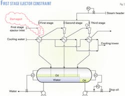
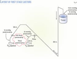
Column operating pressure is set by ejector system capacity (Fig. 3) and only one of the two parallel first stage ejectors operated (Fig. 4). Operating both first stage ejectors overloaded the intercondensers, which raised suction pressure and reduced HVGO product yield. In this case, only the first stage was limiting. Replacing one of the first-stage ejectors and optimizing the configuration of the first stage was a low cost item with a large benefit, assuming the poorly designed column flash zone and wash section internals could be modified at a reasonable cost.
Revamp philosophy
Effective revamps require an understanding of all potential solutions and the creative insight to combine the right ones for the specific circumstances. Pushing major equipment to its inherent safe and reliable operating limit means many equipment details must be reviewed.
Small errors cannot be tolerated, unlike a grassroots design in which significant engineering "fat" is designed into the equipment. CPD is not a cursory study, but a thorough review that identifies low-capital opportunities and fully defines revamp scope.
Revamps are always capital-cost constrained. The designer must find solutions that are economically justifiable and fit within the budget. An engineering study with a scope that exceeds the budget and does not get built is a waste of money. Scope rationalization or value engineering performed after P&IDs are finalized is not an effective way to control costs.
Eliminating major equipment or entire systems in detail engineering will invalidate the revamp design basis and reduce the return on investment. In the worst-case scenario, the revamp will not be operable and an unscheduled shutdown will be needed.
Repsol YPF revamp
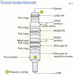
Arriving at the most cost-effective solution for vacuum unit revamps requires balancing the operating temperature, system pressure, and oil partial pressure (Fig. 5). This is an iterative process that is highly dependent on the design, reliability, and condition of the existing major equipment.
The revamp engineer must manipulate the pressure profile from the vacuum system back through the heater inlet while always watching costs. Reducing column operating pressure is an effective way to increase HVGO yield if the column and heat removal systems are not fully utilized.
Prerevamp, the existing column operated at a low capacity factor. Reducing column pressure to the maximum shell capacity factor, therefore, permitted a higher HVGO product yield without raising heater outlet temperature.
The HVGO and LVGO pumparounds' heat removal were not fully utilized and both were increased through operating changes only. Thus, only column internals changes and a new first-stage ejector were needed to lower column flash zone pressure from 28 mmHg to 15 mmHg. These were relatively low-cost modifications.
The next step was to establish whether other low-cost changes would further improve gas oil yields. Once the pressure is decreased, temperature must be increased or oil partial pressure reduced to further raise gas oil yield.
Increasing the heater outlet temperature was not possible without modifying the heater because the coking rate was already at its limit. Coking rate sets heater run length and the amount of cracked gas produced. Cracked gas production cannot exceed the ejector system capacity; otherwise, the whole ejector system would need to be replaced.
Another problem was high transfer-line pressure drop. While increasing temperature improves vaporization, it also raises transfer-line pressure drop. But a higher transfer-line pressure drop increases heater outlet pressure, which suppresses vaporization.
Increasing heater outlet temperature further increases HVGO product yield. Complete heater and transfer-line modeling, however, were needed to quantify the amount. Coil steam would be needed with higher temperature; otherwise the coking rate would reduce heater run-length and overload the ejector system.
Steam injection reduces oil residence time, peak heater bulk oil temperature, and peak oil film tube temperatures. Selecting the correct steam location is critical. It must be injected upstream of the heater tubes with the highest coking tendency, yet far enough downstream in the radiant section to minimize incremental pressure drop to ensure charge pump capacity is not exceeded.
Coil steam also reduces transfer-line vapor molecular weight and increases pressure drop from the heater outlet to the column flash zone. While the steam reduces oil partial pressure and decreases oil residence time in the heater, it also raises heater outlet pressure. Making proper changes to the heater avoids costly changes to the transfer line.
Operating conditions
Increasing vacuum distillate yield upgrades the VTB that feeds the conversion units, which ultimately results in more gasoline, kerosine, and diesel products. Gas oil yield and quality, however, depend on operating conditions and the major equipment design.
Shortfalls in existing process and equipment design often prevent increasing product yields or improving quality. But shortfalls are frequently not noted because insufficient field data are gathered to properly identify them or establish unit operating constraints.
Critical operating conditions of system pressure, temperature, and oil partial pressure all influence vacuum gas oil yield and quality. Manipulating these variables is the key to improving distillate yield. But incremental distillate yield improvements must not come at the expense of run length.
Many vacuum unit revamps produce incrementally higher yields for 2-12 months but then require a shutdown to decoke the heater or replace coked column internals. Most deep-cut vacuum unit revamps do not meet their design HVGO yield, product quality, or run lengths. Heater and column internals coking often causes short run lengths because the problem's root cause was poor fundamental equipment and/or process design.
Major equipment design dictates whether the unit can be reliably operated at a higher temperature, lower pressure, or lower oil partial pressure. Heater outlet and flash-zone temperatures of 800° F. and 775° F., respectively, are possible with proper heater, column, and ejector system designs.
Fired heater performance sets the coking rate and the quantity of cracked gas produced. Ejector capacity determines the system operating pressure. Pressure drop generated by the column internals establishes flash-zone pressure.
Transfer line, flash zone, and wash-section designs influence the HVGO concarbon, metals, and asphaltenes content through their impact on VTB entrainment. They also influence the coking rate in the wash section internals. Column flash-zone design and wash-section capacity factor restrictions determine the minimum system pressure and influence coil steam injection rates.
Cost-effective process and equipment changes must account for the interdependency of all major equipment. Manipulating pressure and temperature require the feed pump, heater, transfer line, column and internals, heat removal, and ejectors to be evaluated together as single system. If not, there may be unwanted surprises.
Ejector system
A consequence of using coil steam is an increased first-stage ejector gas load. The ejector suction pressure was 13 mmHg before the revamp, and no coil steam was being used.10-12 Using coil steam would therefore increase gas load and raise pressure if no changes were made.
The ejector system was either undersized, had a high suction line pressure drop, and/or had mechanical damage. An ejector is similar to a compressor; the motive steam supplies energy to compress the process gas. Motive steam rate increases as suction gas load goes up.
First-stage ejector process gas load, as well as suction pressure and discharge pressure, set the amount of motive steam required for a new ejector. A higher motive and coil steam rate raises inter-condenser duty.
A higher inter-condenser duty could increase cooling water requirements beyond the existing systems' capacity, but cooling tower modifications or a new cooling tower are costly and should be avoided.
After thoroughly reviewing the condensing loads associated with coil steam injection, the existing cooling water system was adequate. The ejector was replaced because an ejector system can be a major constraint to increasing HVGO yield, and the one of the existing first-stage ejectors was performing well below its rated operation. Both first-stage ejectors were put in service, which decreased tower operating pressure and decreased ejector suction line pressure drop (Fig. 4).
Equipment design
An experienced revamp engineer will exploit under-utilized equipment and consider integrated system inter-dependencies and their cost impacts. Raising the heater outlet temperature, decreasing column flash-zone pressure, and injecting coil steam to reduce oil partial pressure were all used to increase gas oil yield.
Fig. 6 shows operating pressures and temperatures after the revamp. Column top and flash-zone operating pressure were 13 and 28 mmHg, respectively, before the revamp. A new first-stage ejector and new wash section column internals allowed the top and flash-zone pressures to be reduced to 5 and 15 mmHg, respectively.
Column capacity factor was increased to 97% of shell capacity, while maintaining constant HVGO product quality. The revamp increased the maximum heater outlet temperature from 750 to 780° F. Coil steam injection at 0.5 wt % of fresh feed reduced oil partial pressure below the 15 mmHg flash zone pressure and further increased HVGO yields.
Coil steam also dramatically lowered oil residence time, thus allowing higher oil film temperature without excessive oil cracking. Controlling heater cracking kept the cracked gas production below the second and third ejector stages capacity.
Heater, transfer line performance
Increasing heater outlet temperature and injecting coil steam raises the heater firing rate, transfer-line pressure drop, heater pressure drop, and peak oil-film temperature in the heater tubes.
The column flash zone to the heater inlet must be evaluated as a single system with a computer model capable of both rigorous heater tube-by-tube rating and two-phase flow calculations that use the critical velocity limit to automatically adjust system pressure. This is important because the heater outlet pressure sets vaporization and, if the system pressure is limited by critical velocity, the heater outlet pressure may be much higher than the pressure calculated using only hydraulic losses.
During a revamp, calculated heater outlet pressure must be correct so that oil vaporization and the calculated pressure profile in the heater are accurate. Controlling the oil residence time and minimizing peak oil-film temperature are essential to meeting target heater run lengths.
A rigorous heater tube-by-tube rating allows the designer to evaluate oil residence time and peak oil-film temperature in each tube. The heater model must predict the effects of pass heat flux imbalances present in most heaters. Otherwise, the model will incorrectly calculate peak oil-film temperature and oil vaporization profile in the two-phase tubes.
Field measurements, such as tube skin temperature or localized heat flux, can also be used to check heater model validity.
Ultimately, the revamp engineer must decide where to inject the coil steam and how much steam to use to suppress coking while not exceeding feed pump hydraulic limits. Choosing the wrong location will cause coking in tubes upstream of the injection point or a high pressure drop, which limits charge rate.
Accurate heater modeling is essential. The influence of heat flux imbalances13 and other nonideal conditions should not be overlooked.
A thorough evaluation of the heater and transfer line provides a low-cost solution to maximize HVGO product yield without a high investment. The solution in this revamp was to relocate coil steam injection from the front of the radiant section to the back of the radiant section (Fig. 7), set the design coil steam rate at 0.5 wt % feed, and raise maximum heater outlet temperature from 750° F. to 780° F.
No transfer line changes were made. The flash zone, transfer line, and heater were modeled as a single system. The revamp engineer set the model's vaporization rate in the flash zone by fixing the total heat needed to meet a targeted HVGO yield.
The model then calculated transfer-line pressure drop including critical velocity limitations, and finally it calculated tube-by-tube peak oil-film temperatures and oil residence times based on the actual heater configuration. The model made the calculations backwards from the flash zone through the heater.
After each run, peak oil-film temperatures and oil residence times in each tube were evaluated to determine if cracking was excessive. If excessive cracking occurred, the flash-zone total heat and coil steam rate were adjusted until an HVGO yield was found that had an acceptable coking rate. This was an iterative process.
Transfer line and heater calculations are complicated, yet they must be done correctly to avoid coking, and to make decisions concerning coil steam injection location and steam rate.
For a given heater design, the pressure profile from the flash zone back through the heater determines how much heat can be added before the oil cracking limit is reached and how much charge rate the existing pumps will handle.
In any vacuum heater, oil vaporization occurs in the last four-to-six tube rows. Pressure also drops quickly in the last four-to-six tube rows while heat is being added. The amount of vaporization depends on tube pressure drop, oil vaporization curve, and system pressure. An approach to critical velocity in the heater outlet tubes further complicates the calculation.
Critical velocity calculation methods are complex. There is a great debate as to whether they should be used and if they have a practical value. Field measurements of transfer-line pressure and temperature, and subsequent calculations using the model, however, confirm that critical velocity is real and does influence transfer-line pressure drop and heater outlet pressure.
Two-phase critical velocity is much lower than the sonic velocity of the gas phase alone; therefore, most transfer lines operate at critical velocity near the heater outlet and at the column's entrance. Whether critical velocity exists at intermediate points depends on the transfer-line design.
Transfer lines usually have long horizontal runs with line diameters of 36 to 84 in. The liquid and vapor phases separate with the phase regime either stratified or stratified wavy. When phase separation occurs, there is contact only at the liquid-vapor interface.
Phase separation causes superheated vapor to flow through the top of the pipe and colder liquid on the bottom. When the superheated vapor enters the vacuum column wash section, the superheat must be removed before heavy oil condensation occurs. Hence, assuming flash-zone equilibrium, this will cause the calculated wash oil rate to be low, which results in dry-out of the packing and rapid coke formation.
Wash section coking14 15 occurs on nearly all columns operating above 750° F. in which the wash rate was calculated assuming equilibrium and the wash bed depth is 5 ft or more. Packed bed depth has a significant influence on coking.
Column flash zone, wash section
As the flash-zone operating temperature and capacity factor increase, the design of internals becomes a critical success factor. Design mistakes have reduced HVGO product yield and caused coking and unscheduled shutdown of numerous vacuum units.
Vapor and liquid feed enters the column at velocities as high as 380-400 fps. The vapor phase contains small droplets of VTB that form in the transfer line. Droplet size is too small and velocity is too high in the transfer line for the droplets to settle.
Ideally, vapor leaving the horn should enter the wash section uniformly distributed across the column cross-section. The vapor must be free of entrainment because it contains high metals, concarbon, and asphaltenes.
Many vacuum columns operate at a low temperature and low capacity factor, which makes flash-zone internals not important. Repsol YPF's revamp, however, increased temperature and raised the capacity factor to increase HVGO product yield. Under these conditions, flash-zone internals need to provide good initial vapor distribution into the wash section and help de-entrain VTB from the rising vapors.
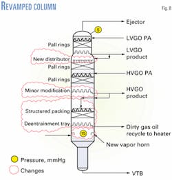
The revamp installed new flash-zone and wash-section internals (Fig. 8). A new, proprietary vapor horn was installed.16 This vapor horn dramatically reduced high-velocity vapor swirling near the vessel wall that would have caused high localized vapor rates.
High vapor velocity areas can prevent the wash section from removing small VTB droplets. This would have caused higher asphaltenes, concarbon, and metals in the HVGO. In addition, localized high vapor rates cause these areas to dry out.
Poor vapor-horn design would have reduced HVGO product yield because the wash oil rate needed would have been higher than the minimum to keep the wash section packing from drying out.
Before the revamp, the wash section used two packed beds and a mesh pad for VTB de-entrainment. The top bed of pall rings and mesh pad were sprayed with HVGO. The lower pall ring bed recycled dirty wash oil from the collector below the bed to a spray header above the bed. The revamp replaced the two beds with a single bed of structured packing using HVGO as wash liquid. This reduced the high pressure drop caused by coking and fouling.
Another problem was that the overflash collector tray leaked. Overflash would quench the flash zone vapor, which reduced HVGO product yield. The collector tray was damaged during each startup because the refractory would expand at a different rate than the tray deck, causing the welds to crack. The refractory design was modified to leave a gap between the refractory and vessel wall so that the tray could expand without damaging the seal welds.
LVGO-HVGO fractionation
The LVGO/HVGO fractionation section packing was retained, but a new high-efficiency liquid distributor was installed above the bed to improve efficiency. Good initial liquid distribution above any fractionating bed is essential because packing itself is not a good liquid distributor. The new distributor allowed a 36° F. increase in LVGO product cut point, which corresponds to a 2 vol % yield improvement.
References
- Hanson, D.W., Lieberman, N.P., and Lieberman, E.T., "De-entrainment and washing of flash zone vapors in heavy oil fractionators," Hydrocarbon Processing, July 1999, pp. 55-60.
- Golden, S.W., Lieberman, N.P., and Martin, G.R., "Correcting design errors can prevent coking in main fractionators," Hydrocarbon Processing, November 1994, pp. 72-80.
- Martin, G.R., Luque, E., and Rodriguez, R., "Revamping crude unit increases reliability and operability," Hydrocarbon Processing, June 2000, pp. 45-56.
- arletta, T., and Nigg, J.M., "Diagnose flooding columns efficiently," Hydrocarbon Processing, July 2001, pp. 71-75.
- Golden, S.W., Craft, S., and Villalanti, D.C., "Refinery analytical techniques optimize unit performance," Hydrocarbon Processing, November 1995.
- Golden, S.W., and Martin, G.R., "Controlling vanadium from high metals crude oils," presented at the 1995 NPRA Annual Meeting, San Francisco, Mar. 18-20, 1995.
- Barletta, T., and Martin, G.R., "Revamping conceptual process design," Petroleum Technology Quarterly, Winter 2001, pp. 41-48.
- Barletta, T., and Martin, G.R., "Improved conceptual process design avoids revamp scope growth," presented at the 2002 NPRA Annual Meeting, San Antonio, Mar. 17-19, 2002.
- Martin, G.R., and Barletta, T., "Vacuum unit fired heater coking-avoid unscheduled shutdowns," Petroleum Technology Quarterly, Spring 2001, pp. 119-25.
- Martin, G.R., "Understand real-world problems of vacuum ejector performance," Hydrocarbon Processing, November 1997, pp. 63-75.
- Martin, G.R., Lines, J.R., and Golden, S.W., "Understand vacuum-system fundamentals," Hydrocarbon Processing, October 1994, pp. 91-98.
- Martin, G.R., and Nigg, J.M, "Vacuum unit pressure control: Impact on refinery profitability," Petroleum Technology Quarterly, Summer 2001.
- Martin, G.R., "Heat-flux imbalances in fired heaters cause reliability problems," Hydrocarbon Processing, May 1998, pp. 103-09.
- Golden, S.W., "Troubleshooting vacuum unit revamps," Petroleum Technology Quarterly, Summer 1998, pp.107-13.
- Golden, S.W., Lieberman, N.P., and Lieberman, E.T., "Troubleshoot vacuum columns with low capital methods," Hydrocarbon Processing, July 1993, pp. 81-99.
- US Patents 5605654 and 5106544 assigned to Koch-Glitsch, Inc.
The authors
Daryl W. Hanson is a chemical engineer with Process Consulting Services, Houston. His responsibilities include process and equipment design and field troubleshooting. He specializes in all phases of refinery distillation from process simulation through field inspection. Previous experience includes lead process specialist for Koch-Glitsch Inc., Dallas, where he was involved with more than 100 column revamps including heavy oils, light-ends recover, and this column revamp. Mr. Hanson has authored more than 20 technical papers on revamping, troubleshooting, and distillation. He holds a BS in chemical engineering from Texas A&M.
Mauricio A. Martin is a distillation and coker unit chief at Repsol YPF's refinery in Lujan de Cuyo, Argentina. He has worked as lead process engineer for the vacuum unit and two atmospheric unit revamps. His experience includes conceptual process design, heat integration network, process simulation, and heat transfer devices. Mr. Martin has been involved in debottleneck, optimization, start up, and field troubleshooting of distillation units. He holds a degree in industrial engineering from Universidad Nacional de Cuyo, Argentina.
