Fieldbus provides advantages for Indonesia waterflood project
Based on a presentation to ISA2001, Sept. 10-13, 2001, Houston.
The waterflood facilities for PT Caltex Pacific Indonesia´s Balam and Bangko oil fields, on Indonesia´s Sumatra Island, included Foundation fieldbus systems that had several advantages over traditional 4-20 ma analog signals, including interoperability among products from several vendors.
As part of the waterfood installation, PT CPI assigned a project team to make a comparative study of analog systems, 4-20 ma, and fieldbus technologies, such as Foundation fieldbus and Profibus.
The decision to install the fieldbus was not easy because there was a risk of failure and some instrumentation experts did not recommend its use. The experts said "Wait a few years until the system is really proven."
PT CPI, however, selected the Foundation fieldbus because the thorough analysis revealed that it provided superior economic, operational, and maintenance advantages.
These were PT CPI´s first Foundation fieldbus applications as well as the first for its parent company ChevronTexaco Corp.
This successful installation has proven many of the advantages of a Foundation fieldbus system, including reduction in design work, programming and configuration time, material and labor cost, installation time, documentation, maintenance, and operational complexity.
Project overview
The Balam and Bangko fields have water-treating plants that condition the injected water before it is pumped to the injection wells. Gathering stations, next to the water-treatment plants, collect the fluids from the producing wells.
The gathering stations include first-stage gas-liquid separators and oil-water separation equipment. The oil enters storage tanks before being transferred to a shipping port for sale.
The water-treating plants include a further oil-water separation stage, with the oil sent for sale and the treated produced water injected into the oil reservoir to improve recovery.
Before waterflooding, PT CPI disposed of the produced water after treating it.
The Foundation fieldbus devices allow all process flows to be monitored and controlled. This includes pressure and differential pressure measurements, flow and level transmitters, and control valves.
The Balam water-treatment plant handles 400,000 bw/d and has 32 fieldbus devices, while the Bangko facility handles 250,000 bw/d and has 26 fieldbus devices.
Both plants have a similar configuration but the distance between the field devices and the control room is greater for Bangko than for Balam.
Both plants use the Fisher-Rosemount DeltaV system as the controller and a human-machine interface (HMI).
Interoperability
Interoperability is the ability tightly to interconnect devices from different manufacturers and have them operate together properly, including sharing the status of variables.
Bangko has Smar LD302, Honeywell ST3000, and Rosemount 3051 transmitters and a Fisher Fieldvue DVC5010 digital valve positioner.
Six junction bricks, separated into five segments, connect these devices, as follows:
- Segment 1-two junction bricks with seven devices connected.
- Segment 2-one junction brick with five devices connected.
- Segment 3-one junction brick with five devices connected.
- Segment 4-one junction brick and four devices connected.
- Segment 5-one junction brick with five devices connected.
Because one H1 (low-speed bus) card handles two segments, the system requires three H1 cards.
The Balam plant has Smar LD302 and Rosemount 3051 transmitters, along with the Fisher Fieldvue DVC5010. All devices are connected to eight junction bricks, as follows:
- Segment 1-three junction bricks and 11 connected devices.
- Segment 2-two junction bricks and 9 connected devices.
- Segment 3-three junction bricks with 12 connected devices.
Foundation fieldbus interoperability of these systems has proven to be successful and is working well, to date.
System comparison
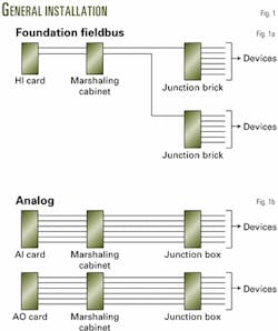
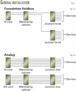
Fig. 1 illustrates typical Foundation fieldbus and analog signal installations and show that the analog system uses more cable to connect between the controller (I/O card) and the devices. Cable length also differs between the installations, and in the analog system some cards differ between the input and output.
Installation advantages of the Foundation fieldbus over an analog systems include:
- Significant reduction in the cost of wiring and in the cost of termination and testing. The fieldbus is a multidrop system.
- Plug and play capabilities. A device is recognized instantly upon connection to the bus.
- Time savings due to remote configuration capability from control room. The fieldbus provides standardized access to device parameters.
- Reduced loading on control room equipment due to the field devices having distributive control and input-output functions.
- Automated documentation.
- Multiple suppliers and vendor.
Operating benefits for the fieldbus are:
- Greater accuracy. The system transmits numeric data in a digital floating-point format, and therefore the data are not subject to analog signal degradation.
- More precision. The fieldbus allows for up to a seven-digit, floating-point data representation.
- Better and safer control. Safeguards detect errors and signal degradation for the digital signal transmission. The analog signals, however, have few or no safeguards, and therefore can cause incorrect actions to being taken because of bad signals.
- Increased information. Multiple signals on a wire provide an expanded view of the process.
- More reliability and security. Errors can be much more reliably detected with digital rather than analog signals.
- Less downtime.
The fieldbus also has maintenance benefits, such as:
- Increased reliability. The system has built-in safeguards to detect errors and failures.
- Competitive replacements and a possibility for interchangeability of devices.
- Automated documentation.
- Remote diagnostics. The fieldbus provides access to numerous parameters within the devices.
But there are some disadvantages of Foundation fieldbus over analog systems, as follows:
- Because it is new technology, not all applications are available in the fieldbus system and analog devices still provide more choices.
- Fieldbus requires more training of installation personnel because it is completely different from analog systems.
- Fieldbus has slower update time than analog systems, especially if many control functions are distributed to the controllers.
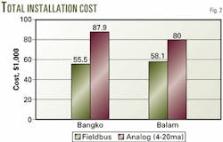
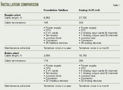
Tables 1 compares installation data between a fieldbus and an analog system for the Bangko and Balam plants. Based on these data, Table 2 presents comparative cost data.
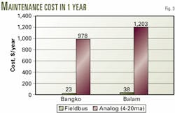
The differences will impact installation, operational, and maintenance costs.
Figs. 2 and 3 show that the Foundation fieldbus has a significant cost saving on both installation and maintenance when compared to analog systems.
Reduced start-up time
Although the project team decided on Foundation fieldbus systems for the Balam and Bangko projects, it did not implement all fieldbus functions. In particular, it decided to use programmable logic controllers (PLCs) for executing the proportional-integral-derivative (PID) control strategy, even though the fieldbus has the capability for true distributed control by having the control algorithms in the devices.
Except for this function, the installed systems included all other fieldbus capabilities. The project team knew the benefits of a distributed control function. But it decided to be conservative and not include this function because these were the first installation of this type and the control system was critical to the success of these multimillion dollar projects.
The installation of the control strategy in the PLCs permitted the distributed control capabilities in the devices to be considered as backups of the PLCs.
During the commissioning and start-up in the Bangko plant, however, project implementation needed to be accelerated. Specifically, the project required that two of the six injection pumps start sending water to the injection wells earlier than initially planned. At that time, the control logic and control strategy in the PLCs had not been tested, and installation remained incomplete on at least half of the discrete cable from the motor control center to the PLC.
The project team evaluated all possibilities for accelerating the project and decided to put the control strategy (PID control) for critical level and pressure loops in the fieldbus devices.
This decision and the ease of implementation provided by Foundation fieldbus allowed the project to attain the earlier start date. Foundation fieldbus gave the project team the capability to commission and download only portions of the overall control strategy. This provided the system with the flexibility of running some of the control loops even though other fieldbus devices and other input-output devices had not been installed.
This implementation allowed the project to add loops or programming at a later date without influencing or risking existing loops. In addition, as mentioned previously, the Foundation fieldbus system required less installation and commissioning time as compared with a traditional analog system.
Lessons learned
Since installation and commissioning of the Foundation fieldbus system in first quarter 2000, there have been many additional lessons learned.
For instance, the shield must be connected to a ground connection at one point only. If the shield is connected to the transmitter body, to a positive-negative cable, or to two ground connections, the communication link will be disrupted and data from the field devices cannot be retrieved.
This condition occurred during commissioning of the system.
The devices did not appear in the configuration screen, and troubleshooting was difficult, requiring a trial-end-error method to find the problem.
Another problem encountered during commissioning was that devices were sometimes detected and sometimes not detected.
After connecting one segment to an H1 card, the installers sometimes noted that one or two devices appeared but at other times no devices appeared. This problem did not occur with one power conditioner connected but did occur with two power conditioners connected in parallel.
The installers eliminated the problem by changing to a different brand of power conditioner. Not all power conditioners, even from the same manufacturer, can be used in parallel.
The installers also had to revise some of the controller and device firmware. For instance, the process values from the Smar devices did not appear after configuring and commissioning the devices.
The controller detected that the device was always in the "out of service" mode, although the device had been configured to be in the "auto" mode. The installers after checking the controller found that the firmware revision was not the latest. After they downloaded the latest controller firmware revision, the Smar transmitters started to successfully communication with the DeltaV controller.
A similar problem appeared after installation of the Honeywell transmitters. These devices could not be commissioned, even though the transmitters appeared on the list of live fieldbus devices. These devices started to work properly, only after downloading the latest device firmware revision.
Although all transmitters communicated properly, not all parameters can be retrieved and displayed on the HMI. Only common parameters can be retrieved and displayed.
For ease of commissioning, one should note the device identification (ID) number and tag name during installation. Not knowing the device ID number causes difficulties after power is applied because all the devices in a segment appear at the same time without identifying the tag name for a particular device ID number.
One also must install a terminator at the end of the segment if the trunk length is more than 300 ft. Failure to install the terminator will result in the inability to retrieve field device data because of excessive noise.
Based on the lessons learned, it is recommended that the following activities be performed during installation and commissioning:
- Ensure that each device has the firmware revision and device data description, which is compatible with the controller.
- Calculate fieldbus network power consumption to determine voltage drop and to verify that the fieldbus network meets fieldbus regulations.
- Ensure the use of good power conditioners.
- Ensure that the shielded cable is connected to the ground at only one point.
- Ensure that the positive and negative cable connections are terminated properly, except for devices that have no polarity sensitivity.
- Ensure that a terminator is installed at the end of a segment.
- Use a fieldbus tester to check the fieldbus wiring and network condition.
- Write down device ID numbers and the associated device tag name during installation.
The authors
Ivan Susanto is a facility engineer with PT Caltex Pacific Indonesia, Riau, Indonesia. Susanto has a BS in electronics and telecommunications from Trisakti University, Jakarta, Indonesia. He is a member of ISA and a member of Foundation Fieldbus end users.
Imam Purwanto is a facility engineer with PT Caltex Pacific Indonesia, Riau, Indonesia. Purwanto has BS in electrotechnics from Bandung Institute of Technology, Indonesia. He is a member of ISA.
