Saudi well study derives optimal gas well configuration parameters
Zillur Rahim
Adnan Al-Kanaan
Hamoud Al-Anazi
Saudi Aramco
Dhahran
A study of Saudi gas wells led to quick and simple analytical solutions for determining well geometries that improve productivity.
This article covers the effect on reservoir productivity from such factors as reservoir permeability, vertical anisotropy, net pay thickness, horizontal well length, fracture half length, fracture conductivity, number of finite transverse fractures induced in a horizontal wellbore, and other relevant parameters.
Although the results obtained from the analytical solutions are somewhat optimistic because they do not consider damage or operational issues, the results are a reference to assess qualitatively the effect of different completion types on reservoir performance.
Saudi gas wells
Saudi Aramco has been exploiting its gas reservoirs for the past decade with hydraulically fractured vertical and horizontal wells.1-6 Comprehensive geomechanical models have allowed predicting correct drilling mud weight, optimizing perforated interval selection and fracture design.4 5
Current development strategy includes drilling horizontal wells and completing them with multistage fracturing.3
Many wells have horizontal laterals placed in the maximum horizontal stress (σmax) direction to minimize risks associated with well integrity during drilling and production life. Some horizontal wells completed in relatively tight formations often include hydraulic fracturing for improving production.
Horizontal wells drilled toward the minimum horizontal stress (σmin) offer a better chance that fracturing will obtain more production.3 Hydraulic fracturing parallel to σmin will induce transverse (orthogonal) fractures to the wellbore, thus ensuring better reservoir contact with the formation and allowing for the possibility of creating many fractures without compromising fracturing efficiency.
A pilot program already has indicated success of this strategy. Evaluation of actual well performance depending on well geometry and configuration is ongoing for different fields, reservoirs, and fluid systems.
The key performance index evaluated to ensure the success of a development program is the long-term sustained productivity of a well. Comparison of the productivity index among various completion types is essential for selecting the most appropriate drilling and fracturing program.
Numerous models in the industry approximate fluid flow for vertical wells, horizontal wells, and wells that are fractured hydraulically.7-12
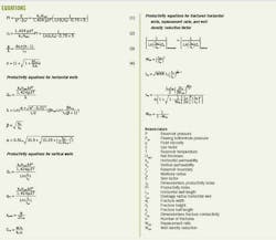
Productivity index
The pseudosteady state Equation 1, in the equation box, defines the productivity index (PI) of a vertical gas well with an openhole completion.
Equation 1 can be written as Equation 2 after defining a dimensionless productivity index JD as the inverse of the term ln[(re/rw) – 0.75 + S].
With introduction of the effective wellbore radius concept, one can compute JD for different completion configurations as follows.
1. Vertical wells without fracture and openhole completion (Jv).
2. Vertical wells with induced fracture covering the entire pay section (Jvf).
3. Horizontal wells with openhole completions (Jh).
4. Horizontal wells with a finite number of induced transverse fractures covering the entire pay section (Jhf).
The ratio of JD between two wells with different completion types indicates a well performance contrast among wells.7 JD values are constant for a certain geometric configuration and are independent of some reservoir properties, but the flow rate Qg and PI values are not. These values vary and mainly depend on reservoir flow capacity, depletion, pressure behavior, and heterogeneity.
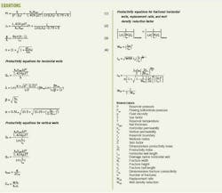
The equation box contains a summary of equations for well inflow performance for different well and reservoir characteristics.
Unstimulated vertical wells perform reasonably well in high-permeability reservoirs and can outperform horizontal wells if a reservoir is thick and layered (low vertical to horizontal permeability ratio, kv/kH), and the horizontal well reservoir contact is not significantly large.
Flow patterns in a vertical well are cylindrical, while in a horizontal well they are ellipsoidal. The different patterns lead to different drainage volumes and performance.
PI equations
The equation box contains the productivity equation for a horizontal well producing from a reservoir with vertical anisotropy β.
One should note that β is different from the vertical to horizontal reservoir permeability contrast kv/kH usually referred to in simulation models. As such, when the ratio kv/kH decreases, the vertical anisotropy actually increases.
Similarly, the equation box also lists the productivity equations for unfractured and fractured vertical wells.
The vertical wells covering the entire pay section either through openhole completions or perforations are independent of vertical anisotropy because the flow is always in the horizontal or radial direction.
One can calculate the fracture width by knowing the total amount of proppant pumped during the treatment and assuming that the job generates linear symmetrical planar vertical fracture on two sides of the wellbore, towards σmax. In this case, wf = V/hfxf, which is subsequently used to compute Cfd.
In the case of tight reservoirs, the treatment should induce multiple transverse fractures for improved connectivity and production. These wells will produce at uneconomic rates if only drilled horizontally and left open hole.
The productivity equation (Equation 3) assumes the total induced vertical transverse fractures n in a horizontal section of length LH and that all production is from the induced fractures.
For given values of n, xf, and LH, one can easily compute the productivity increase of a fractured horizontal well over an unfractured open hole from the equations in the equation box, assuming the entire section of LH contributes to production when completed open hole.
For a given wellbore configuration, one also can compute the number of vertical fractures required in a horizontal well to match production from an openhole wellbore. The assumption in this case is that the fracture orientation is transverse to the horizontal wellbore (wellbore drilled toward σmin) and that flow is linear from the reservoir to the fractures and then radial to the well in the fracture plane. For horizontal wells without fractures, on the other hand, production is through the entire wellbore because of the open hole.
Equation 4 calculates the number of fractures required in a horizontal fractured well to equal the production from an openhole horizontal well.
For a hydraulically fractured vertical well, the apparent wellbore radius rwa can replace the actual wellbore radius rwd. One can calculate rwa from the desired fracture length, proppant volume, and expected fracture width.
Prat's correlation can solve for rwd, which in turn is used to compute rwa.8
PI comparison
Various combinations of well geometry and reservoir properties result in different well performance ratios.
For a horizontal well, the main assumptions in this article are:
• Laterals are completed open hole.
• The open hole produces from its entire length LH.
• Flow behavior is elliptical.
• Drainage radius is the distance from the middle of the horizontal section to the elliptical boundary.
For a vertical well, the assumptions are that the well is completed through the entire pay section and that it will drain more or less in a circular pattern.

A horizontal well fractured transversally will have flow that converges to the well through induced fractures. Fig. 1 illustrates the boundary shape, position of the vertical and horizontal wells, and transverse fracture orientation in horizontal wellbores.
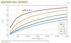
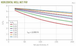
Fig. 2 shows the PI ratio between a horizontal and vertical well for a vertical anisotropy kv/kH of 0.1, drainage radius 1.2 times horizontal well length, and net pay thickness varying from 20 to 200 ft. Note that a longer horizontal section adds to higher production; the thicker the net pay, however, the lower the efficiency of horizontal wells over vertical wells, assuming all the pay section is open to the wellbore.
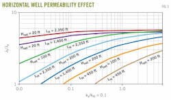
Horizontal wells become more effective with a decrease of anisotropy (Fig. 3) because improved vertical permeability favor horizontal wells.
Also Fig. 3 shows that for the same lateral lengths, horizontal wells have better deliverability in thin reservoirs with more anisotropy. Of course the efficiency of vertical wells also depends on well spacing and the effective drainage area.
The curves in Figs. 3 and 4 assume a reservoir length of 1.2 times the horizontal well length and equal vertical and horizontal drainage areas.
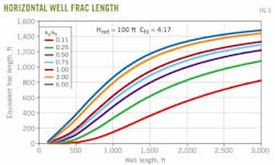
Fig. 4 illustrates that in thick reservoirs the effect of a horizontal well is more significant in favorable kv/kh contrast. Fig. 5 shows the fracture half length required in a vertical well to match horizontal well performance. Effective fracture half lengths in excess of 400-500 ft with reasonable conductivity (comparable skin factors of –6 or less) are extremely difficult to achieve. Hence, the benefit of horizontal wells for improved productivity is evident.
The ratio of horizontal to vertical well productivity, Jh/Jv, decreases if the vertical wells are hydraulically fractured. A 1,500-ft horizontal well will produce about the same as a vertical well with a 200-ft fracture half length and a vertical anisotropy of 0.1, where Jh/Jvf = 1. If the vertical permeability is higher, the same well can produce about 40% more than the fractured vertical well.
For horizontal wells, the fractures are perpendicular to the wellbore plane, and the higher reservoir contact provides the best improved productivity in tighter formations.
For thin reservoir sections, the benefit of fractured horizontal wells is insignificant because the unfractured openhole wells can efficiently drain a thin reservoir. This is shown by increased net pay thickness indicating the need for fracturing the horizontals to communicate with the entire thickness. For example, four 100-ft vertical fractures will not show any improvement over a 2,000-ft openhole horizontal wellbore completed in an isotropic medium kv/kH = 1. This conclusion will change when any of the assumptions change.
Another conclusion is that few vertical fractures, three or less, in a long horizontal well are not beneficial because the fractures cannot compete with production from the openhole section.
This assumes that unfractured horizontal wells produce from their entire openhole section whereas fractured horizontal wells produce only from induced fractures. This is true when a fractured horizontal well is completed with cemented liner and perforated only in the treatment intervals.
With increased anisotropy, shorter net reservoir contact, and thick pay sections, however, the need increases for fracturing horizontals even with a fewer number of fractures.
Computer runs made for two vertical fractures in the horizontal well indicate that in a 1,000-ft horizontal section with 300 ft of net pay, the JD ratio is twice in favor of a fractured horizontal well. For a 2,000-ft horizontal section, however, two vertical fractures are not enough to improve the production over an openhole completion, provided the well can produce without a fracture treatment.
Replacement ratio, well density reduction
Replacement ratio WRR and well density reduction WDR are inversely related and also are important performance indicators for justifying initially a horizontal well drilling project, if drilling horizontal wells is feasible.11 The main variable is the productivity indices, set equal for horizontal and vertical wells, for calculating the number of wells needed in each category for draining a certain radius in the field.
Iterative solutions of the equations for WRR and WDR, in the equation box, can compute the values of the ratios.
Fig. 6 illustrates the analytical solution to show the number of vertical wells avoided by the drilling of openhole horizontal wells with different reservoir contacts.
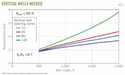
For the example runs, the drainage area of vertical wells varies between 10 and 120 acres. To avoid horizontal wells going beyond the drainage area, we assume that the drainage area for such configuration is 1.1 times the wellbore length LH.
Fig. 6 shows that long horizontal wells can replace many vertical wells. Also due to low permeability, the vertical well spacing must be much smaller for optimal drainage. In such a case, the benefit of horizontals is even more pronounced.

Fig. 7 shows the replacement ratio as a function of net pay thickness. Again, the horizontal wells drain more efficiently in less thick reservoirs. A 1,500-ft horizontal wellbore will replace two and four vertical wells draining 20 acres in 200 and 20 ft of net pay thickness, respectively.
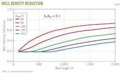
If the spacing is larger, the replacement ratio will be smaller. Fig. 8 shows the well density-reduction curves for different reservoir configurations.
Horizontal, fractured vertical wells
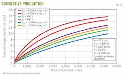
Figs. 9 and 10 plot the gas rate and cumulative gas production for isotropic and anisotropic reservoirs, different horizontal well lengths, and various fracture half lengths for vertical wells.
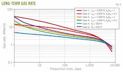
For a 0.1-md tight reservoir with no vertical anisotropy, a 3,000-ft openhole horizontal (Case 1) produces at about 20 MMscfd after 10 days as compared with 10 MMscfd if the vertical permeability is 10% of horizontal permeability (Case 2). The same 10 MMscfd is obtained from a vertical well with a 400-ft fracture half length (Case 6). The instantaneous potential at the onset of production for this fractured well, however, matches Case 1.
The cumulative production plots (Fig. 10) show the preference of openhole, long, horizontal wells in cases of negligible vertical stress anisotropy. For kv/kH of 0.1, which is usually a default value in reservoirs with unassessed vertical heterogeneity, a vertical well with a 400-ft fracture half length (Case 6) can outperform a 1,000-ft horizontal well without fractures (Case 4).
After 20 years, ultimate recovery will be about 30% more for the vertical well. On the other hand, Case 2 (3,000-ft horizontal well) will produce about 15% more than Case 6 due to the higher reservoir contact. As discussed previously, the productivity depends on several other factors such as net pay thickness, reservoir permeability, and the anisotropy factor.
Tight-gas reservoirs
Currently Saudi Aramco produces gas from moderate to high-permeability conventional reservoirs. The stabilized rates at very high wellhead pressures can vary anywhere between 10 and 80 MMscfd. The well spacing of such prolific reservoirs can be about 2-3 km (980-2,280 acres in a square drainage configuration) between wells. These reservoirs have a high ultimate recovery.
The company, however, now is embarking on developing its tight gas from shale and very low-permeability sandstone and carbonate reservoirs. Tight gas is usually defined with respect to reservoir permeability and its potential to be produced economically after a stimulation treatment. For effective drainage, the well spacing also is limited, between 40 and 80 acres. The ultimate recovery is much lower than for conventional reservoirs.
Tight-gas reservoirs developed by drilling of vertical or horizontal wells require hydraulic fracturing for commercial production rates. For a given field, the well spacing to drain certain geometric areas greatly affects the ultimate production in a reasonable time span, such as 20 to 30 years. Other than reservoir permeability and well density, the volume of gas Vgas = ϕ × Hnet × A × (1 – Swi – Sgirr) as well as initial reservoir pressure affect ultimate recovery.
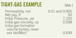
A 20-year production forecast for cumulative production in a constant pressure drawdown case for two low-permeability cases, 0.005 and 0.01 md (Table 1), shows that the recovery of about 25% of the gas is the best scenario case (horizontal well with skin = –3 and kH = 0.01 md). For the same scenario, a vertical unfractured well will recover only 8% of the gas.
Estimated ultimate recovery as well as average well rates for a tight-gas reservoir is relatively low, so that there is a need to reduce well spacing and increase the number of wells to meet target rates and improve recovery within a reasonable time. Tight reservoirs will not produce without multistage fracture treatments.
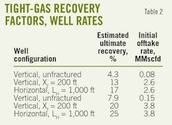
Table 2 lists estimated tight-gas recovery factors and estimated well production rates.
Production history
The productivity indices of several wells drilled with horizontals and stimulated with multistage fracturing (MSF) confirm the success of these treatments.1

Fig. 11 shows the PI from four wells with similar permeability and reservoir development, two of which had MSFs in three stages. The two remaining wells also have good PIs but have slightly lower performance than the MSF wells.
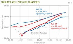
The half slopes from the pressure-transient test analyses from the two MSF wells clearly indicate the presence of induced fractures (Fig. 12). The calculated aggregate effective fracture half lengths are 900 and 500 ft, respectively. The productivity improvement from drilling and fracturing, as needed, of horizontals is a key driving factor for selecting optimal completion type.
Although a well in a moderate to high permeability reservoir (k > 1 md) can produce 50 bcf or more of gas, a well in a tight reservoir will produce only 1-2 bcf during 20 years.
One should note that due to the different well spacing used in developing conventional and tight reservoirs, one conventional well can produce an order of magnitude more than one tight-gas well, of course from a much larger drainage system.
A properly designed well and stimulation treatment in an unconventional reservoir can outperform a poorly configured well by several folds.
Well spacing, wellbore configuration, and type of hydraulic fracturing will depend not only on reservoir properties (heterogeneity) but also on the kh and the expected production rate and recovery.
Acknowledgment
The authors thank Saudi Aramco management for the permission to develop this analytical model and for allowing this article to be published.
References
1. 2009-11 Gas Program, Saudi Aramco gas reservoir management division internal documentation.
2. Rahim, Z., Al-Anazi, H., Malki, B., and Kanaan, A., "Optimized Stimulation Strategies Enhance Aramco Gas Production," OGJ, Oct. 4, 2010, p. 66.
3. Rahim, Z., et al., "Openhole multistage fracturing boosts Saudi Arabia gas well rates," OGJ, June 6, 2011, p. 66.
4. Al-Qahtani, M.Y., and Rahim, Z., "A Mathematical Algorithm for Modeling Geomechanical Rock Properties of the Carbonate and Pre-Khuff Reservoirs in Ghawar Field," Paper No. SPE 68194, SPE Middle East Oil Show, Bahrain, Mar. 17-20, 2001.
5. Rahim, Z., et al., "The Role of Geomechanical Earth Modeling in the Unconsolidated pre-Khuff Field Completion Design for Saudi Arabian Gas Wells," Paper No. SPE 84258, SPE ATCE, Denver, Oct. 5-8, 2003.
6. Rahim, Z., Al-Qahtani, M.Y., and Buhidma, I., "Improved Gas Recovery from Acid of Hydraulic Fracturing," Saudi Aramco Journal of Technology, Spring 2001, pp. 50-60.
7. Diyashev, I., and Economides, M., "The Dimensionless Productivity Index as a General Approach to Well Evaluation," SPE Production & Operations, August 2006.
8. Prats, M., Hazebroek, P., and Strickler, W., "Effect of Vertical Fractures on Reservoir Behavior—Compressible-Fluid Case," Society of Petroleum Engineers Journal, June 1962.
9. Mukherjee, H., and Economides, M., "A Parametric Comparison of Horizontal and Vertical Well Performance," SPE Formation Evaluation, June 1991.
10. Joshi, S.D., "Augmentation of Well Productivity With Slant and Horizontal Wells," JPT, June 1988.
11. Giger, F.M., "Low-Permeability Reservoirs Development Using Horizontal Wells," Paper No. SPE 16406, SPE/DOE Low Permeability Reservoirs Symposium, Denver, May 18-19, 1987.
12. Wei, Y., and Economides, M., "Transverse Hydraulic Fractures From a Horizontal Well," Paper No. SPE 94671, SPE ATCE, Dallas, Oct. 9-12, 2005.
The authors


More Oil & Gas Journal Current Issue Articles
More Oil & Gas Journal Archives Issue Articles
View Oil and Gas Articles on PennEnergy.com