New NGL-recovery process provides viable alternative
Robert R. Huebel
Michael G. Malsam
Randall Gas Technologies
Houston
| Based on a presentation to the GPA Europe Annual Conference, Prague, Sept. 21-23, 2011. |
Operational scenarios for two uses of a new refrigeration process for recovering NGLs from natural gas have shown it to enhance operability and reduce capital and operating expenditures when compared with the two more traditional process choices—straight refrigeration and turboexpander.
Straight refrigeration units that most often use propane as refrigerant have proven to be economical and reliable. Their operating temperature, however, typically about –35° F., limits NGL extraction. For higher NGL recovery, today’s processor is left with a cryogenic turboexpander.
IPOR (IsoPressure Open Refrigeration) has been developed by Randall Gas Technologies, a division of Lummus Technology, a CB&I company, to bridge this gap. The advanced refrigeration process can economically achieve essentially total C3+ recovery from most natural gas streams. Using conventional closed-loop mechanical refrigeration combined with an open-loop mixed refrigeration cycle, the new technology can achieve NGL recovery efficiencies comparable to that of advanced turboexpander cycles but for lower capital and operating expenditures.
This article reviews the fundamentals of the IPOR process, including process features, benefits, and applicability. It also presents case studies that compare process performance with both straight refrigeration and advanced turboexpander cycles and economic analysis.
Diverse environments
Natural gas conditioning and processing plants are somewhat unique in that the raw material feedstock is typically fed into the plant at the pressure, flow rate, and composition at which it is produced.
Consequently, natural gas processing plants have considerable variation in size, complexity, and configuration, depending upon specific reservoir production characteristics, geography, customer specifications, and market drivers. These range from simple dewpoint plants with capacities less than 5 MMscfd and minimal hydrocarbon recovery to large deep cut ethane extraction straddle plants which process in excess of 1 bcfd .
With such a diverse operating environment, it is a bit surprising that natural gas processors have had essentially only two process technology choices for extracting hydrocarbon liquids from natural gas: either straight refrigeration or turboexpander. Among more than 1,600 operating natural gas processing plants shown in Oil & Gas Journal’s Worldwide Gas Plant Survey, about 80% use either straight refrigeration or turboexpander technology (OGJ, June 6, 2011, p. 88).
With the last new lean oil plant built some 30 years ago, the estimated portion of new gas plants built today using these two technologies is greater than 95%.
Straight refrigeration units, which most often use propane or ammonia, can be built for essentially any capacity or feed-gas composition, are of mild steel construction, are relatively simple to construct and operate, and have proven to be economical and reliable. However, with their operating temperature typically limited to about –35° F., their capability for NGL extraction is limited.
For higher NGL recovery, today’s processor has but a single choice: cryogenic turboexpander. Since its inception in the late 1960s, turboexpander technology has evolved into the technology of choice for deep NGL-product recovery. As designs were refined, turboexpander technology essentially displaced lean-oil technology for high LPG or ethane-extraction applications.
Several variations of the technology are available, depending upon the targeted product recovery and feed-gas conditions, with proprietary designs offering even higher efficiencies. With operating temperatures as low as –200° F., NGL product recoveries approaching 98%+ are technically feasible.
With straight refrigeration technology, the benefits for the customer include low capital and operating expenditures (CAPEX and OPEX), a broad range of applicability, early production capabilities, but limited NGL recovery. Expander technology offers superior NGL-recovery potential but higher CAPEX and OPEX and a longer time to initial operation due to the long lead time of such specialty equipment as the turboexpander and brazed aluminum heat exchangers.
Ethane-rich cycle
The advanced refrigeration NGL extraction process can economically achieve deep NGL extraction from most natural gas streams. Using conventional closed-loop mechanical refrigeration combined with an open-loop mixed refrigeration cycle, this process can provide performance comparable to that of advanced turboexpander technologies but with much lower CAPEX and OPEX.
Unique about the IPOR process is its open-loop ethane-rich mixed refrigeration cycle. This refrigerant, extracted from the feed gas itself, is a mixture of predominantly ethane with lower concentrations of methane, propane, and other feed-gas constituents.
This refrigeration cycle serves a dual purpose: producing the cryogenic refrigeration for the process to enable lower temperature operation while at the same time providing a reflux stream to the fractionation column, the combination of which produces high product extraction and thermal efficiencies.
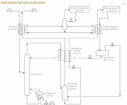
The extraction process can be configured in several ways, depending on the feed stream, site conditions, and project objectives. Fig. 1 depicts one configuration of the IPOR technology recommended for high recovery LPG applications.

Feed gas, at a pressure typically 300-550 psig, is initially cooled and partially condensed in the gas-gas heat exchanger by cross exchange with cold residue gas and propane refrigerant. A conventional brazed aluminum heat exchanger appears in the flow diagram; however, shell-and-tube exchangers can also be used for this service.
The cooled and partially condensed feed-gas stream is then fed to the middle section of the de-ethanizer, which uses either trays or packing or a combination of these to effect the desired product separation. Below the feed tray, the stripping section of the column selectively removes the lighter fractions to meet product specifications, which normally is 2-5% ethane in the recovered propane. Heat for the separation is provided by the de-ethanizer reboiler, which is a conventional shell-and-tube heat exchanger, with the heat supplied from the plant heating medium system.
In the upper section of the de-ethanizer, above the feed tray, the cooled feed gas flows counter-currently to the reflux stream, which is fed to the top tray in a conventional manner. The reflux provides additional cooling for the feed-gas stream and also selectively absorbs the propane and heavier components from the gas, thereby providing high product recovery efficiencies.
The overhead gas stream from the de-ethanizer, at this point in the process containing primarily the light ends from the feed-gas stream and a small portion of the propane, is further cooled in the de-ethanizer overhead condenser by cross exchange with cold residue gas and the ethane-rich mixed refrigerant stream.
The cooled and partially condensed gas stream flows to the de-ethanizer overhead separator. The liquid from this separation, a mixture of methane, ethane, and propane, is used as the refrigerant for the open-loop mixed refrigerant cycle. The de-ethanizer overhead separator therefore has a twofold function: It acts as a conventional two-phase gas-liquid separator, and it provides surge capacity for the liquid mixed refrigerant system.
From the de-ethanizer overhead separator, the pressure of the liquid mixed refrigerant is reduced, creating a Joule-Thomson refrigeration effect: This cold stream provides the desired cooling in the de-ethanizer overhead condenser. The pressure of the low-pressure mixed refrigerant, usually in the range of 100-200 psig, is selected to satisfy the cooling requirements in the de-ethanizer overhead condenser and to minimize the compression power requirements.
From the de-ethanizer overhead condenser, the mixed refrigerant stream is heated further as it flows through the mixed refrigerant gas-gas exchanger to the mixed refrigerant compressor. The discharge pressure of this compressor is normally about 40 psig higher than the operating pressure of the de-ethanizer.
The mixed refrigerant compressor is of conventional design and can be either reciprocating, centrifugal, or screw type, depending upon project requirements and customer preferences. Drivers may be gas turbine, gas engine, or electric motor. The compressor can be packaged with driver, scrubbers, and discharge cooler following standard industry practice.
The compressed ethane-rich, mixed refrigerant stream is then cooled and partially condensed in the mixed refrigerant gas-gas exchanger. Cooling for this exchanger is provided by low-temperature mixed refrigerant and propane. The two-phase stream flows to the de-ethanizer reflux drum, a conventional two-phase gas liquid separator. This liquid is used to provide reflux to the de-ethanizer column, thereby completing the "open" cycle of the mixed refrigerant loop.
Noncondensable vapors, consisting mainly of methane, are directed back into the process via the de-ethanizer overhead separator and eventually exit the process into the residue gas stream or may be used as fuel.
The closed-loop propane refrigeration is of conventional natural gas industry design and construction. In a typical IPOR process, the process refrigeration temperature is in the range of –10° F. to –20° F.; other refrigerants, therefore, such as ammonia may be used as well.
For the LPG-recovery configuration above, product extraction efficiencies are excellent, with C3 recovery in the range of 95-99%+, with essentially 100% recovery of the C4+ fraction.
From a thermal efficiency perspective, the IPOR process requires about 15-40% less compression power than a comparable turboexpander design. As a result, plants using the IPOR technology will also have lower emissions and a smaller carbon footprint.
The process utilizes equipment and materials that are all well proven within the natural gas processing industry. Most of the unit can be of carbon steel or low-temperature carbon steel construction; typically the only major equipment item that requires stainless steel construction is the de-ethanizer overhead separator.
The only rotating equipment required for the IPOR process is the refrigerant compressor. The process requires no cryogenic turboexpander or light hydrocarbon pumps. As a result:
• Reliability and operability will be comparable to that of a conventional refrigeration process and should exceed that of a modern day turboexpander facility, given the fewer items of rotating equipment.
• The process offers superior economics for almost any feed-gas rate, from as low as 5 MMscfd to 1 bcfd+.
• Almost infinite turndown capacity is possible with an IPOR process, to feed-gas rates as low as 10% of design, limited only by the performance of in-line control instruments, i.e., control valves, meters, etc., unlike turboexpander designs, which suffer from an inherent loss of efficiency at reduced flows.
The process can be designed for a wide variety of feed-gas compositions, site conditions, and capacities. Ethane recovery can be incorporated into an IPOR process design, with ethane recoveries up to 80%, depending upon feed-gas composition. Equipment can be incorporated to allow for future ethane recovery, or the initial design can permit operation in ethane-rejection/ethane-recovery mode.
The process was developed based on proven technologies and equipment employed extensively in gas plants. All the equipment incorporated into the process design is well within the natural gas industry’s experience and capability. The low equipment count, small footprint, and process simplicity of the technology permit a compact layout and a high degree of modularization.
Marcellus plant
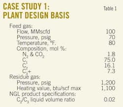
A recent study compared the IPOR process with modern turboexpander technology. Feedstock for the new plant is from the Marcellus shale, a region with limited existing oil and gas infrastructure and no existing ethane market. Demand for LPG in the region is strong, with extracted LPG sold into the local market.
As a result, the customer wanted to maximize LPG production. Due to the richness of the gas, some ethane extraction was required to meet the residue-gas pipeline specifications, with the ethane consumed within the plant as fuel. The field’s gathering system operated at low pressure, with residue gas delivered into an existing high pressure pipeline.
Table 1 summarizes the design basis for the plant.
Two process technologies were evaluated: conventional turboexpander and the IPOR process.
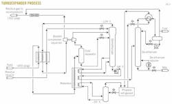
The turboexpander process utilized in the study was a modern design (Fig. 2). Due to the richness of the feed gas, a propane refrigeration system with a low stage operating temperature of –35° F. at 3.4 psig was integrated into the process design to provide supplemental cooling. A portion of the ethane vapor stream from the overhead of the de-ethanizer column is consumed as fuel to achieve the residue-gas heating value specifications.
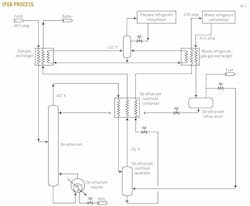
Fig. 3 illustrates the IPOR process used in the study. Feed gas enters the process unit at a compressor interstage pressure of about 365 psig. The propane refrigeration system operates at –10° F., much warmer than that required by the turboexpander process, and 16.7 psig. The minimum operating temperature of the de-ethanizer column is –42° F. and is of low-temperature carbon steel construction.
To achieve the residue-gas pipeline heating value specification, a portion of the ethane-rich noncondensable vapors from the de-ethanizer reflux drum is consumed as fuel, with the remainder mixing with the residue gas via the de-ethanizer overhead separator.
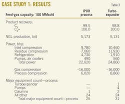
Tables 3 and 4 summarize the results of the study.
Compared with the turboexpander design, the IPOR process:
1. Achieves higher NGL recovery.
2. Requires about 32% less process compression power.
3. Requires about 20% less major equipment.
4. Requires less rotating equipment.
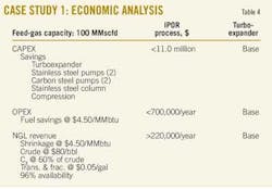
As a result, economics of the IPOR process are clearly superior to the turboexpander design, both from an OPEX and a CAPEX perspective (Table 4). Estimated capital cost of the IPOR process design was $11 million less than that of the turboexpander plant, the savings being the result of:
1. Less installed compression.
2. No turboexpander.
3. No light hydrocarbon/cryogenic pumps.
4. No stainless steel demethanizer column.
5. Less alloy material.
From an operating cost perspective, the IPOR process was estimated to consume about $700,000/year less in utilities, the savings resulting from lower compression power requirements, and hence fuel gas consumption.
Northwest Canada
A second study was recently completed comparing the IPOR process to a straight refrigeration process. Location for this plant is in northwest Canada, an area of existing oil and gas production but no NGL or ethane pipeline infrastructure. Liquids produced in the plant would be trucked to market.
The primary objective of the customer in this application was to deliver a marketable sales gas. Given the current favorable economic climate for gas liquids, however, incremental LPG recovery was of interest if economical.
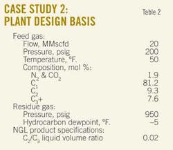
The basis of design of the plant for the study is discussed below. Table 2 summarizes the design basis.

The straight refrigeration process used in the study was a traditional design (Fig. 4), with process temperature selected to achieve the pipeline dewpoint specification, thereby minimizing both CAPEX and OPEX. Propane was used as the refrigerant, with glycol injection used for hydrate inhibition and dehydration. Feed gas for the refrigeration unit was taken downstream of the feed-gas compression, with residue gas sent directly to the sales gas pipeline.
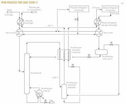
Fig. 5 illustrates the IPOR process used in the study. Feed gas enters the IPOR unit at a compressor interstage pressure of about 410 psig. For this design, the gas-gas exchangers and chillers were conventional shell-and-tube design. All of the noncondensable vapors from the de-ethanizer reflux drum flow to the de-ethanizer overhead separator and on to the residue gas stream.
Tables 5 and 6 summarize the study’s results.
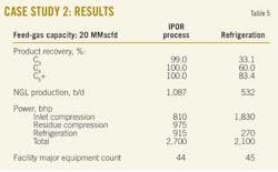
From these results, key observations include the following:
1. NGL production with the IPOR unit is more than double that of the refrigeration plant.
2. Complexity of the two designs is comparable, based upon major equipment count, which should result in similar operability and reliability.
(Major equipment count in this case includes the entire plant facility, including dehydration, utilities, and off sites.)
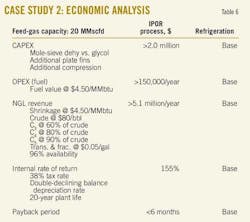
As a result, economics of the IPOR process are once again superior to the refrigeration unit, taking into account incremental differences in both OPEX and CAPEX (Table 6). Estimated capital cost of the IPOR process design was $2 million more than that of the refrigeration plant, the additional cost being the result of:
1. More installed compression.
2. Additional heat-exchanger costs.
3. Additional cost of the molecular-sieve dehydration system vs. the glycol injection system utilized in the refrigeration plant design.
4. More alloy materials.
The operating cost of the IPOR process was estimated to be about $150,000/year more than the refrigeration process. The additional cost was primarily the result of the higher compression power requirements of the IPOR process, and therefore more fuel-gas consumption.
NGL production with the IPOR unit is more than double that of the refrigeration plant. The value of this additional NGL revenue was estimated at $5.1 million/year. Based upon the economic assumptions itemized in Table 6, the calculated internal rate of return of the IPOR plant investment is 155%, with a payback of fewer than 6 months.
While the IPOR unit requires somewhat more CAPEX and OPEX than a "minimal type investment" of the refrigeration unit, these costs are more than compensated for with the increased NGL revenue.
Table 7 summarizes the comparisons discussed in this article.

References
1. Malsam, Michael G, "IPOR Technology—A new means of LPG recovery," Gas Processors Association Annual Convention, "High Definition at 90—Advancing the Midstream Vision," March 2011.
2. "Gas Processing with Cryogenic Turboexpander Technology," Randall Gas Technologies, Houston; January 2011 Edition.
The authors


More Oil & Gas Journal Current Issue Articles
More Oil & Gas Journal Archives Issue Articles
View Oil and Gas Articles on PennEnergy.com