Seismic stimulation improves production from West Texas carbonate

Jeff Marshall
Abraxas Petroleum Corp.
San Antonio
Sergey Kostrov, Bill Wooden
Applied Seismic Research Corp.
Plano, Tex.
A project on a West Texas lease shows the effectiveness of seismic stimulation to arrest oil production rate decline of a nonwater-drive carbonate reservoir.
As worldwide demand for oil increases, oil companies are employing costly methods such as gas injection, chemical injection, and thermal techniques to enhance oil production in large oil fields. In smaller fields, however, these methods, including waterflooding, are often too costly, leaving operators few options to enhance recovery.
The US has an abundance of small oil fields. These fields contain more than 340,000 wells, many producing less than 5 b/d; yet in total these fields produce 260 million bbl/year. The country, therefore, has an untapped potential for increased oil production from small oil fields. The question is what method can be applied to economically enhance oil recovery?
This article covers seismic stimulation for enhancing oil production from a carbonate on Abraxas Petroleum Corp.'s Bishop-Huddleston lease in West Texas.
Waterflooding is a viable option for this lease. Abraxas, however, wanted a less expensive EOR method to recover additional resources. Hence, it chose seismic stimulation because the technology:
• Has zero environmental effects.
• Requires no specialized transport or implementation.
• Stimulates production across many faults and horizons.
• Most importantly, is reliable and inexpensive.
In addition, seismic stimulation has proven effective on diatomite, sandstone, and carbonate reservoirs. The Texas Railroad Commission also certifies it as an official EOR process, thus granting Texas operators a 50% severance tax reduction for 10 years.
Seismic stimulation tool
A conventional pumping unit powers Applied Seismic Research's (ASR's) tool for creating downhole high energy, seismic stimulation shockwaves.
One can install the tool at 700-10,000 ft depths in abandoned wellbores or active injection wells using a perforated sub. The wellbores need to have 5.5 in. or greater IDs.
Tool life span ranges from 8 months to greater than 1 year, depending on wellbore and fluid conditions.
ASR ships the tool in three preassembled sections in a 2 by 2 by 25 ft container. Installation of the tool is similar to a tubing pump. Tool operation requires no major maintenance.
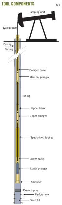
Fig. 1 shows the tool's components. At the bottom of the well, sand fill covers the perforations. Above the sand fill, a placed cement plug prevents gas from entering the wellbore. Gas entry would cause the tool to misfire.
Acoustically, cement is similar to carbonates and the shockwaves do not lose significant power as they pass through the plug.
The shockwaves travel at more than 1.5 miles/sec and compress and release only a small amount of water; hence, the momentum of the traveling wave fronts is so small that they will not damage the cement bond or wellbore integrity.
An amplifier at the bottom of the tool, with a similar design to a rocket nozzle, increases the velocity and modifies other characteristics of the shockwaves.
The lower plunger contains a traveling valve to bring fluids in. When it reaches the top of the stroke, it exits the lower barrel to release instantaneously the highly compressed fluids, thus creating the hydroimpact shockwave. Specialized tubing acts as a compression chamber.
The upper plunger has no pathway for fluid travel and remains in its barrel to act as a seal. The tubing, damper barrel, and plunger create a dampening system to decelerate the upward velocity that the system experiences on firing. More importantly it maintains a minimum 2,500-lb load on the pumping unit to prevent zero loading.
The operator can monitor the tool operation with a dynamometer card, a direct measurement of the load on the pumping unit. This load relates to the loads the tool creates during its compression and release cycles.
The shape of the dynocard tells ASR precisely how the tool is operating downhole.
Periodically, perhaps twice during the tool's lifespan, ASR will request the operator to adjust the setting of the polished-rod clamp to modify tool behavior. This is the only maintenance required on the tool.
The pumping unit sizes range from Lufkin 456 to 912, having stroke lengths from 120 to 168 in., and set speeds of 5 spm.
The load placed on the pumping unit is 10,000 lb above rod weight (at the top of stroke). The unit runs 12 hr on and 12 hr off to give the reservoir a relaxation period that enhances oil droplet mobilization.
Seismic stimulation
Reports of low-frequency, high-energy elastic waves mobilizing oil date from the early 1950s when earthquakes were shown to increase oil production by as much as 45%. The first man-made low-frequency, high-energy source used to mobilize oil was a Russian surface vibroseis in the early 1980s.
Detailed Russian field studies using surface vibroseis proved oil could be successfully mobilized and more importantly the mobilized oil came from the virgin reservoir area; thus, the application of low-frequency, high-energy elastic waves is an enhanced oil recovery method.
In 1998, Los Alamos National Laboratories (LANL) showed only a small pore pressure disturbance, less than 70 Pa (0.01 psi), could increase the permeability of a saturated porous medium and mobilize trapped fluids; hence, the process does not need elastic waves with large magnitudes to improve oil production.
In real terms, seismic stimulation has improved oil production and oil cut in wells as far away as 1.4 mile from the well in which the tool was installed.
The mechanisms describing the process of mobilizing oil under low-frequency, high-energy elastic wave fields center on two main phenomena:
1. Dislodging oil droplets from pore walls.
2. Coalescence of two or more droplets or thin oil films into one of higher mobility.
During the past decade, ASR has performed dozens of field studies and has proven the tool's effectiveness in diatomites with microdarcy permeability and unconsolidated sandstones with darcy permeability. The studies included oil gravities from 11 to more than 40, depths from 700 to 8,000 ft, and GORs from the low 100s to more than 3,000 scf/stock-tank bbl.
In general, permeability and oil gravity (viscosity) govern the time for observing a response. Mobilization of oil with a gravity below 14 is unlikely.
Gas content above 3,000 scf/stock-tank bbl tends to limit areal coverage; however, vibroseis stimulations of gas fields have succeeded. ASR did one successful gas field stimulation in the Austin chalk.
ASR believes, but has yet to pilot, seismic stimulation for improving recovery in unconventional reservoirs such as oil and gas shales and methane from coalbeds. The technology also may have an application in carbon-dioxide floods, alkaline-surfactant-polymer floods, and steam-assisted gravity drainage projects.
Bishop-Huddleston
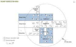
The Bishop-Huddleston project area (Fig. 2) is in Sharon Ridge (Clearfork) field about 10 miles southwest of Snyder in Scurry County, Tex. The producing intervals are the Glorietta at about a 2,300-ft depth and the Clearfork at about a 3,100-ft depth.
The first Glorietta-Clearfork tests on the tracts were in the late 1940s with cable tool rigs. These tests resulted in marginal production due to the relatively poor stimulation techniques available at the time. More successful development was in the mid to late 1950s with application of hydraulic fracturing.
A third development period was in the mid 1970s and early 1980s, probably spurred on by rising oil prices.
Waterflooding began in Sharon Ridge about 1977 and expanded over the years to include most of the field lying to the south of the project area. The flooding to date has been on a lease-by-lease basis by numerous operators. While the response to flooding has varied in the areas nearest to the project, the better areas have had secondary recoveries equal to primary recoveries.
Area geology
Examination of well logs, cores, sample logs, and production data of Sections 161 and 162 reveals the structure and character of several distinct productive and continuous zones of porosity in both the Glorietta-Upper Clearfork and Lower Clearfork.
Structural mapping of the Glorietta and Clearfork shows a north-northeast to south-southwest trending saddle positioned on the common boundary of Sections 162 and 161.
West of this saddle, the structure drops off rapidly into the Midland basin. On the east is a relatively flat area resting on the edge of the Eastern shelf, with a slight structural high in the southeast quadrant of Section 161.
The porosity zones typically have dolomitic porosity, consisting of common pinpoint to occasional vugular porosity created by diagenetic alteration of limestone and lime cement in the sandstones to dolomite due to the presence of anhydrite.
Glorietta, Upper Clearfork reservoir
The Sharon Ridge 2,400-ft reservoir in this area has five sand zones in the Glorietta and three dolomite zones in the Upper Clearfork at 2,300 and 2,600 ft in the Huddleston B No. 8 well. Each zone correlates fairly well on the neutron log and generally consists of 2-10 ft intervals with good neutron porosity often separated by 2-10 ft intervals of poor porosity.
These intervals typically have good sample and core oil shows, and previous operators generally perforated these intervals.
Zone AA is the shallowest and has an apparent sandy zone that has poor definition on core and sample data. Operators have rarely perforated this zone. It follows a general northeast-southwest trending pattern of channels and pinchouts and is not continuous over the entire project area.
Zones A, B, C, and D are all sheet sands that appear to cover the entire project area. Net porosity in these zones seems thickest in the west half and especially the southwest quadrant of Section 161.
Zones E, F, and G appear to be dolomite with no sand. The zones extend over the entire project area and probably were originally limestone that had unique character, such as being oolitic or fossiliferous, that favored dolomitization.
Operators typically perforated these lower zones in only the more recent completions, and these zones generally have greater water production on the initial test.
Lower Clearfork reservoir
The Sharon Ridge Clearfork reservoir in this area has eight dolomite zones (Lower Clearfork) between 3,100 and 3,300 in the Bishop A No. 7 well. Each zone correlates fairly well on neutron logs and generally consists of thin 15-ft intervals with good neutron porosity often separated by 1-5 ft intervals of poor porosity.
Sample and good core shows generally occur in these intervals and previous operators generally chose to perforate them. The intervals typically appear thicker and less interbedded with poorer porosity than the 2,400-ft zones.
The wells on the east half of Section 162 are more recent (1970s), and almost all have all of the porosity from Zone 2 down to Zone 9 drilled and perforated. Although most of these wells produced about 50% water on initial test, some tested oil at good rates with only a small amount of water, further supporting the theory that many porosity intervals in these zones are isolated both laterally and vertically.
Reservoir analysis
In this area, only sparse reservoir data are available. Most Sharon Ridge well logs are cased hole logs, making quantitative log analysis difficult if not impossible. Fortunately, the area has several whole core analyses available that have proven helpful in lithology and reservoir description. The area has only basic reservoir fluid data and no reservoir pressure data available. As mentioned previously, the Glorietta interval is a dolomite with interspersed anhydrite and sand layers. The best reservoir properties occur in the sand layers, where porosities range from 13 to 20% and permeabilities are as high as 10 md.
The dolomitic intervals are dense and tight with average porosities about 13% and average permeabilities of less than 1 md.
The Lower Clearfork is a dense, tight dolomite with some anhydrite inclusions and no sand layers. Core and sample descriptions commonly report vugs with some fracturing observed. Both the Clearfork and the Glorietta require hydraulic fracturing for commercial production rates.
Installation
The seismic stimulation used the inactive Bishop-Huddleston B-9 well as the source well because of its central location in the field; Fig. 3 shows the well completion.
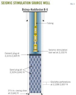
Note that the seismic stimulation tool is completely isolated from the formation with no direct hydraulic connection. This is a typical installation of the tool.
The shockwaves pass through the cement plug and sand with minimal losses in power, but isolation from the formation guarantees that no foreign matter or gas will enter the tool and cause problems.
On firing the shockwaves pass through the cement plug and sand fill before exiting the perforations in the Glorietta at 2,338-2,607 ft.
Simulation results
Fig. 4 shows the results of seismic stimulation on the Bishop-Huddleston lease.
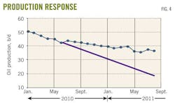
Seismic stimulation improved oil production by 17 b/d, which as of August 2011 equates to an estimated increase in oil recovery of 4,100 bbl.
ASR expects to see the same results in other formations and highly fractured fields with horizontal wells having multiple fractures that due to complex heterogeneities would have in waterflooding early watering out of producing wells.
Tax credits
In Texas, the Texas Railroad Commission gives a 50% reduction in severance tax for a period of 10 years on secondary and tertiary enhanced oil recovery projects that prove a sustained positive improvement in oil production. It bases the tax credit on total oil production within the project area and includes new oil production from infill drilling within the project area.
TRC approved Abraxas' EOR positive production response certification application on Aug. 23, 2011, with the certification date being retroactive to Aug. 1, 2010.
The authors


More Oil & Gas Journal Current Issue Articles
More Oil & Gas Journal Archives Issue Articles
View Oil and Gas Articles on PennEnergy.com